
|
|
|
I know nothing about this additional prototype:
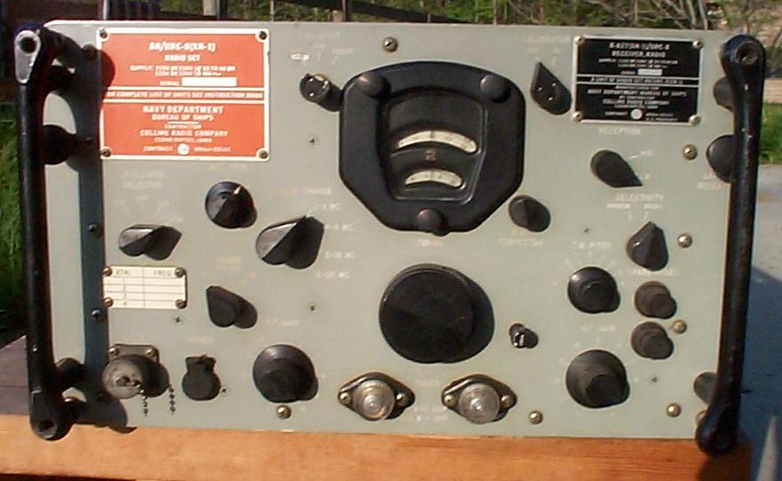
AN/URC-8 (XN-2) Trans-Receiver Radio Set.
CBS LABS NEW YORK
NAVSHIPS 92927
Info from John K4OZY:
First, a thousand thanks to Ken Bodensteiner @ Rockwell/Collins who came up with
some advertising brochures for the URC-8. Turns out it was intended as a
replacement for the TCS! You can view the brochures by clicking here: URC8
Brochure [PDF File]
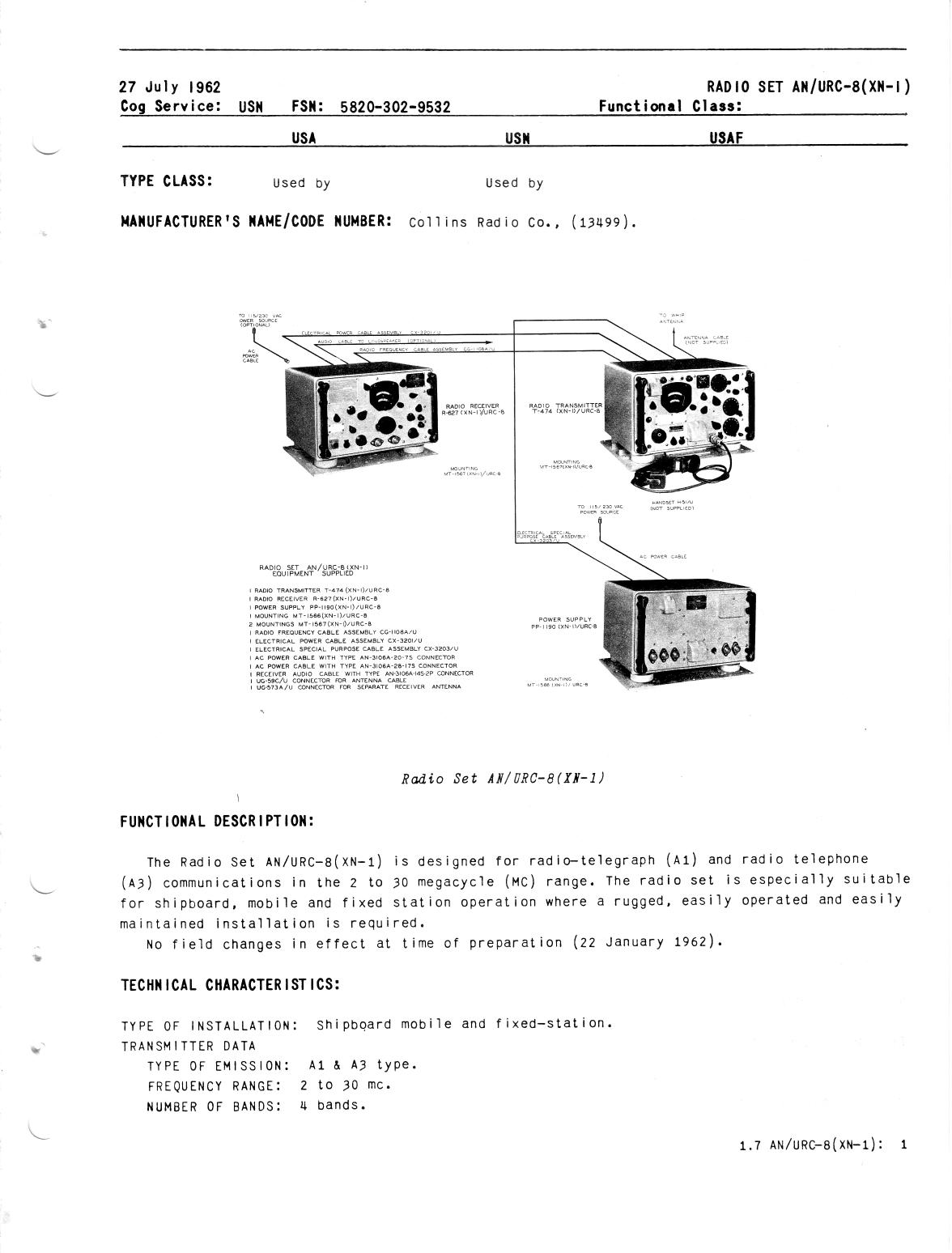
URC-8 consists of
| Mil Name | Collins Part # | Description |
|---|---|---|
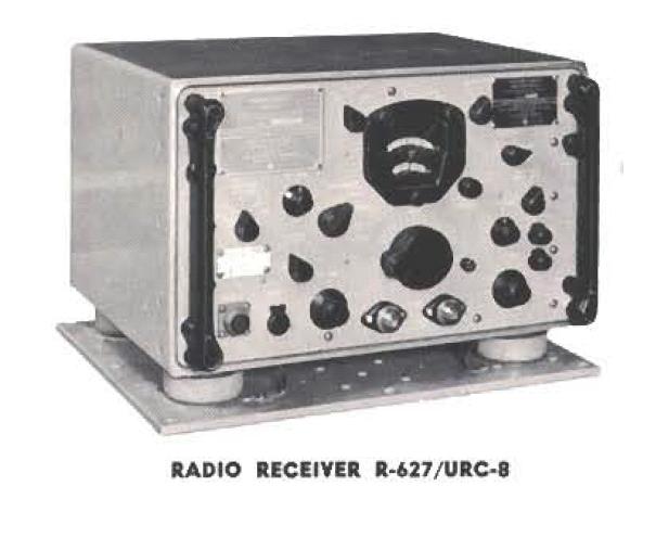
| R-627 | 522-9273-004 | Receiver, 2-30 Mc, 4 bands, AM/CW only, 2 mech filters, 107 lbs PTO or xtal control internal p/s - 115/230 v ac input 50-60 or 400 cps |
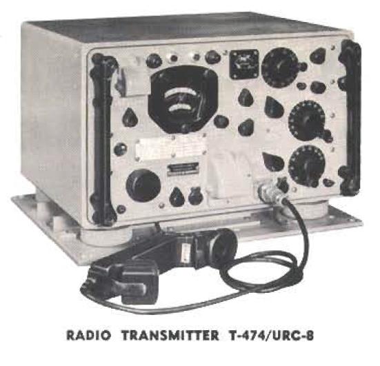
| T-474 | 522-0583-006 | Transmitter, 2-30 Mc, AM/CW, 102 lbs PTO or xtal control 42w output to 15-35' whip antenna |
| PP-1190 | 522-0584-006 | Power supply for transmitter, 137 lbs 115/230 v ac input 50-60 or 400 cps |
| Optional Motor-Generators | ||
| PU-340(XN-1)/U | -- | 12 v dc input |
| PU-340(XN-1)/U | -- | 28 v dc input |
| PU-340(XN-1)/U | -- | 115/230 v dc input |
Thanks to Jim Jones (W0NKN) @ Rockwell/Collins for the Collins P/N's! URC-8 is listed on various military equipment lists, which generally say that the receiver requires PP-1190. This is clearly not the case, as the receiver has an internal power supply (see pix below). The PP-1190 must, therefore, power the T-474. There's also an auxiliary DC Converter (187 lbs) that allowed running the set off a variety of DC and AC supply voltages.
The manuals are NAVSHIPS 92831 and 92927 (1957). Robert Downs (THANKS!) supplied the following additional info:
| Old Number | New Number | Description |
|---|---|---|
| NS 92831 | -- ? | RADIO SET AN/URC-8(XN-1), IB 26 JUL 1956 |
| NS 92927 | 0280-LP-417-2000 | RADIO SET AN/URC-8(XN-2), IB JAN 1957 |
Anyone know the cross-reference for the 92381 document?
If you have ANY information about this receiver or the URC-8 equipment group, please send me mail
T-474(XN-1)/URC-8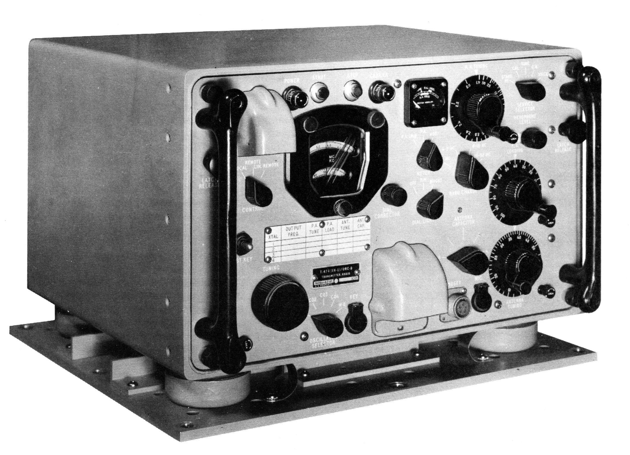 |
T-474(XN-1)/URC-8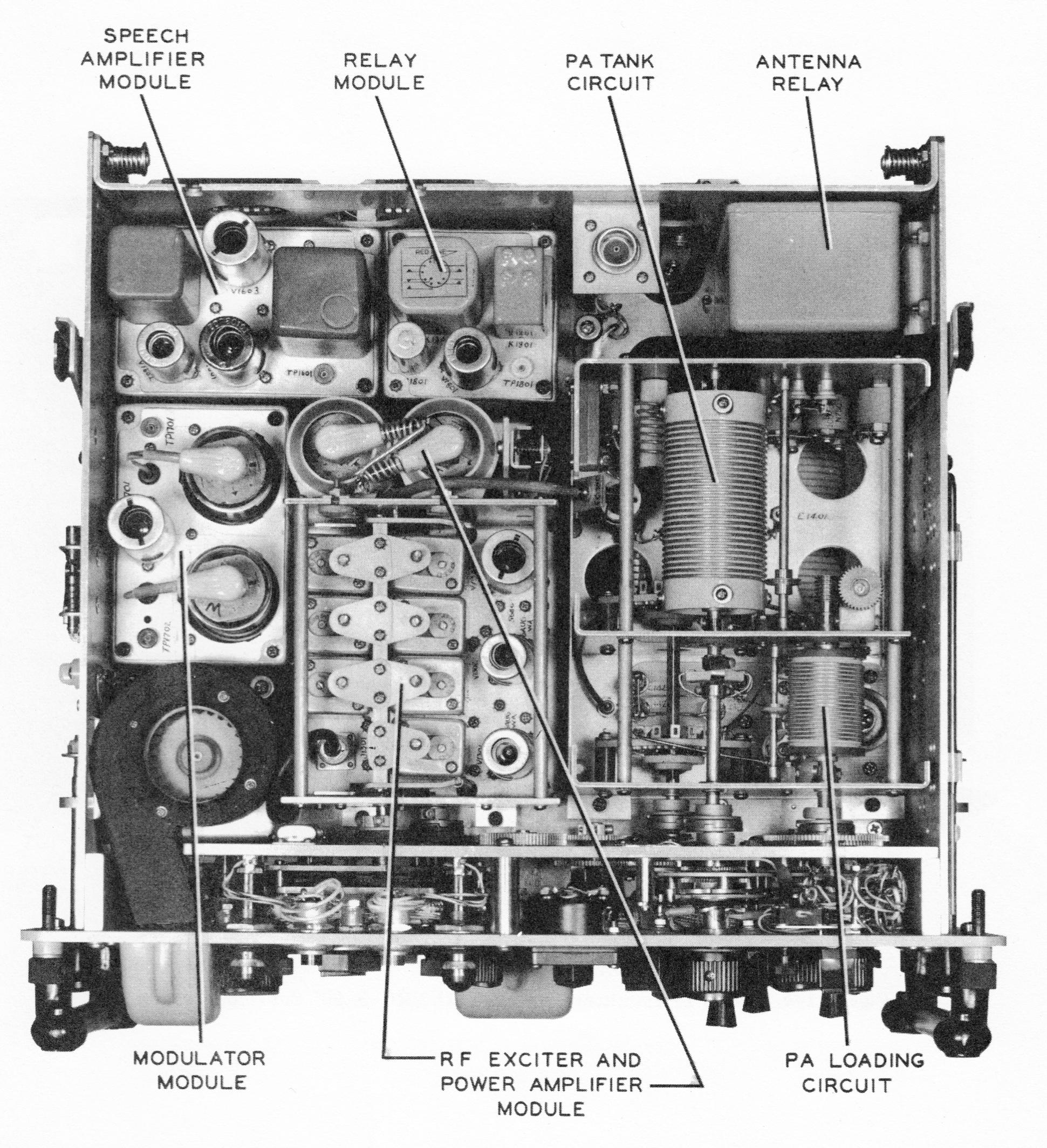 |
T-474(XN-1)/URC-8 |
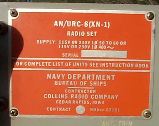
R-627(XN-1)/URC-8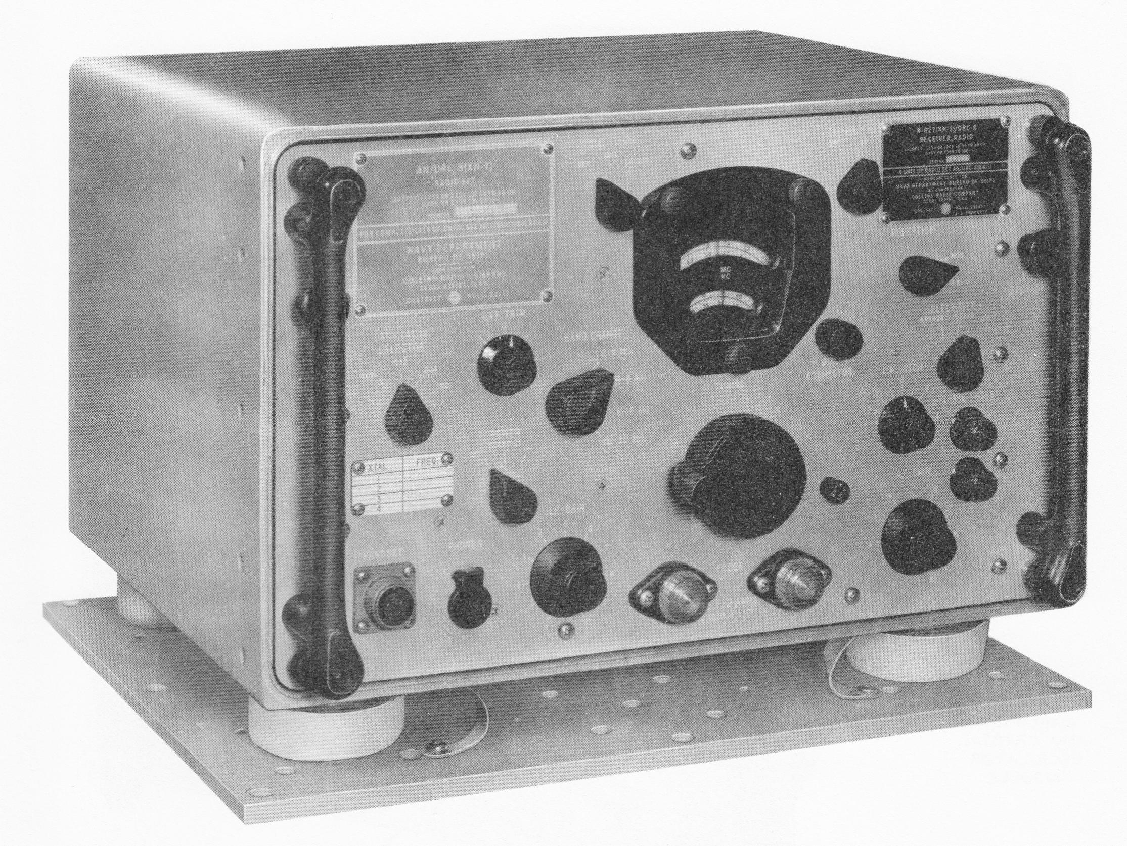 |
R-627(XN-1)/URC-8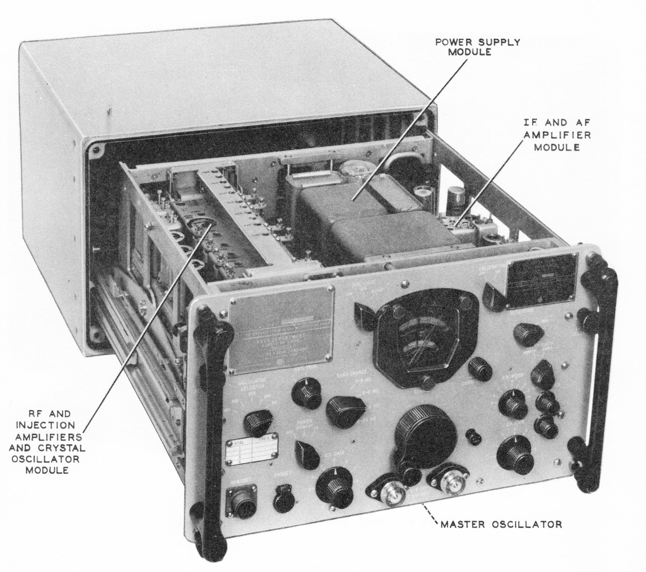 |
PP-1190(XN-1)/URC-8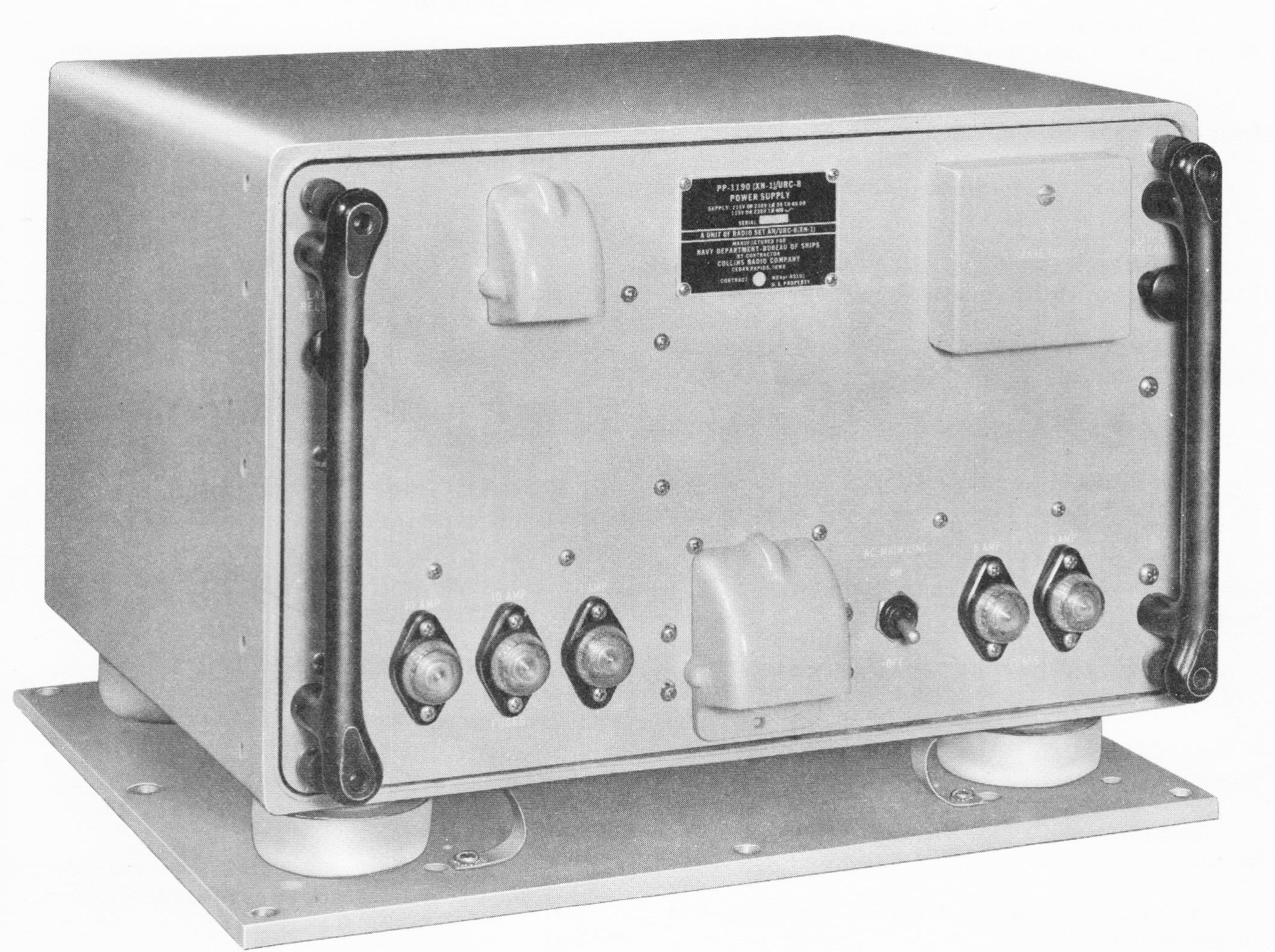 |
Nick's June 2011 notes on R-627/URC-8 s/n 4 - Dual conversion, general
coverage 2-30 mc in 4 bands.
One piece of info says 455kc 2nd IF and there are two empty mechanical filter
sockets in the IF/BFO/AF module
There is a 70H-10 PTO (2.58-4.58 mc) as the HF oscillator.
I had been trying to figure out the conversion scheme and beyond figuring the
PTO was multiplied as follows, had been scratching my head as I saw only one
crystal socket that could act as the fixed LO for the 2nd converter.
Band (mc) multiplier
PTO x multiplier (mc)
2-4
x1
2.58-4.58
4-8
x2
5.16-9.16
8-16
x4
10.32-18.32
16-32
x8
20.64-36.64
Then eureka, I finally found 4 xtals buried deep within the RF deck - this is a
really compact bugger, but with flashlight and magnifier I managed to read the
freqs. Here is my guess at the conversion scheme - using mid-band for
illustrative purposes.
(freq in kc)
RF input PTO x mult 1st-IF
XTAL 2nd-IF
3000
3580
580 1035
455
6000
7160
1160 1615
455
12000 14320
2320 2775
455
24000 28640
4640 5095
455
Yep, I found a couple of IF transformers with 4 coils/housing so it probably
really does have a different 1st IF for each band.
And the extra xtal socket I had identified earlier is for the 100kc calibrator
xtal.
Specification Sheets |
|||
 |
|

|
|
|
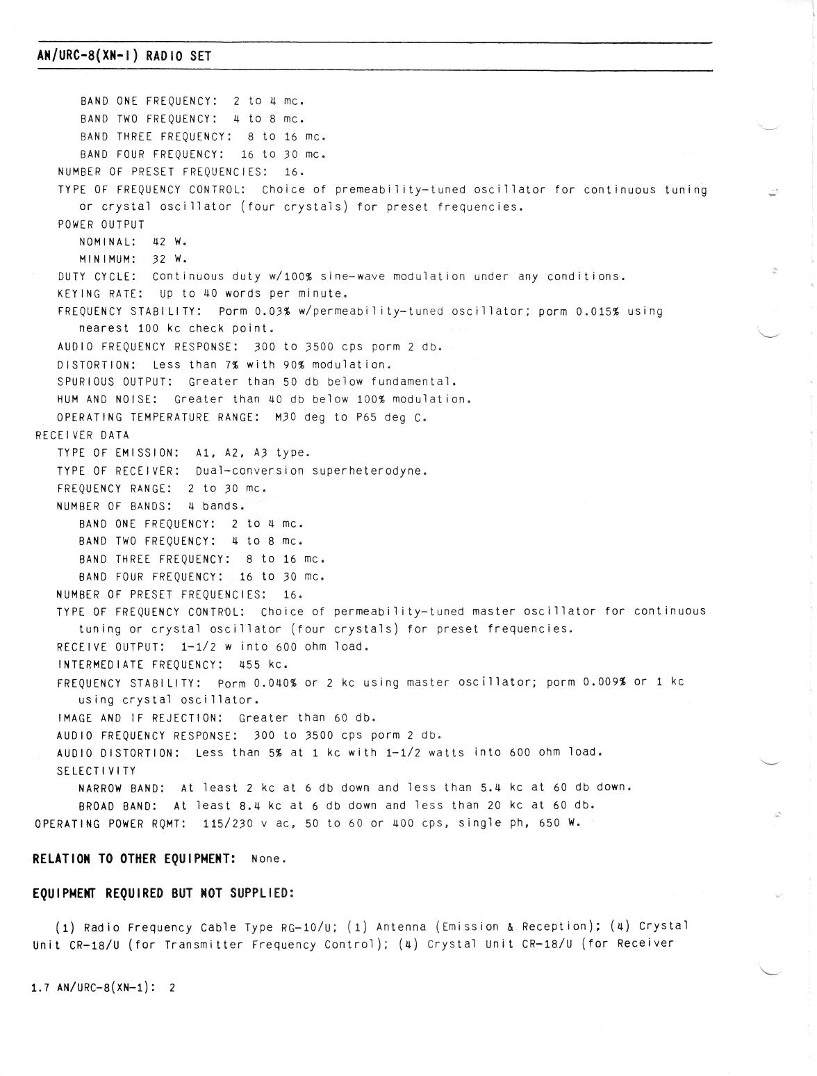
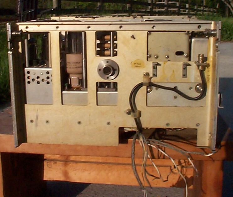
R-627/URC-8 Front view
|
Serial number 4
|
Serial number 4
|
Rear view
|
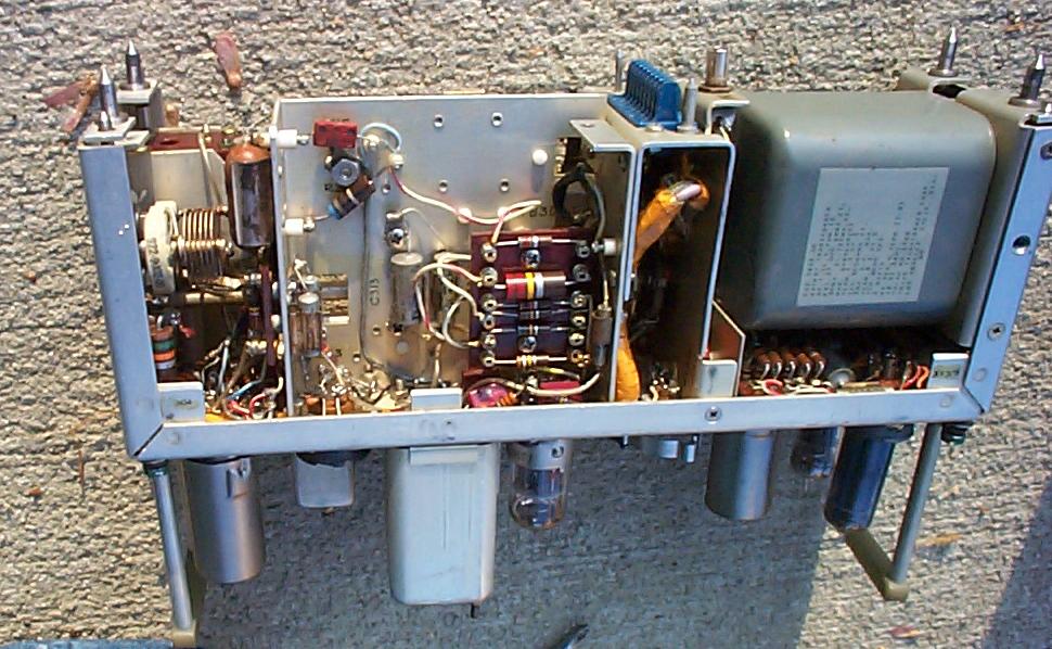
| The receiver uses modular construction somewhat like that employed in the R-390A. There's an RF, IF/AF, and power supply module, secured into the mainframe with the famous green screws. | |||
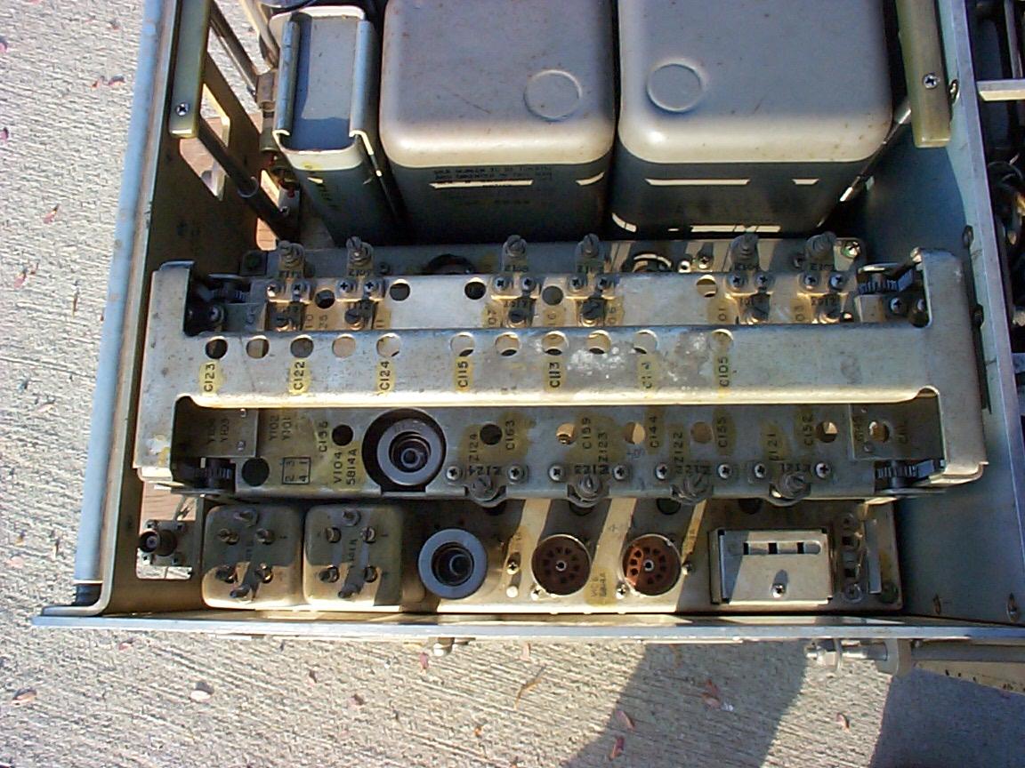
| Top left view, showing RF module at bottom of photo:
|
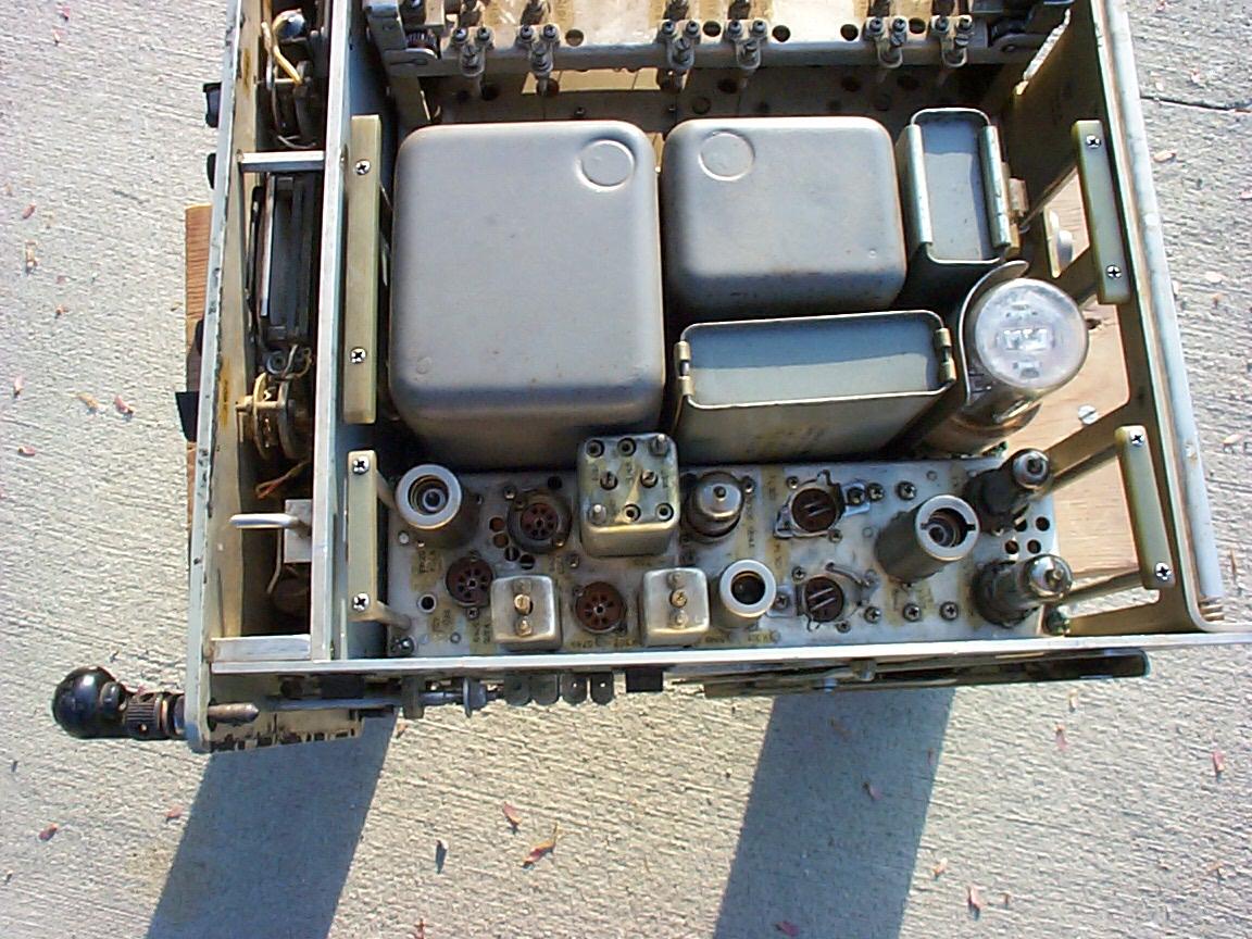
Top right view, showing IF/AF module at bottom of photo:
|
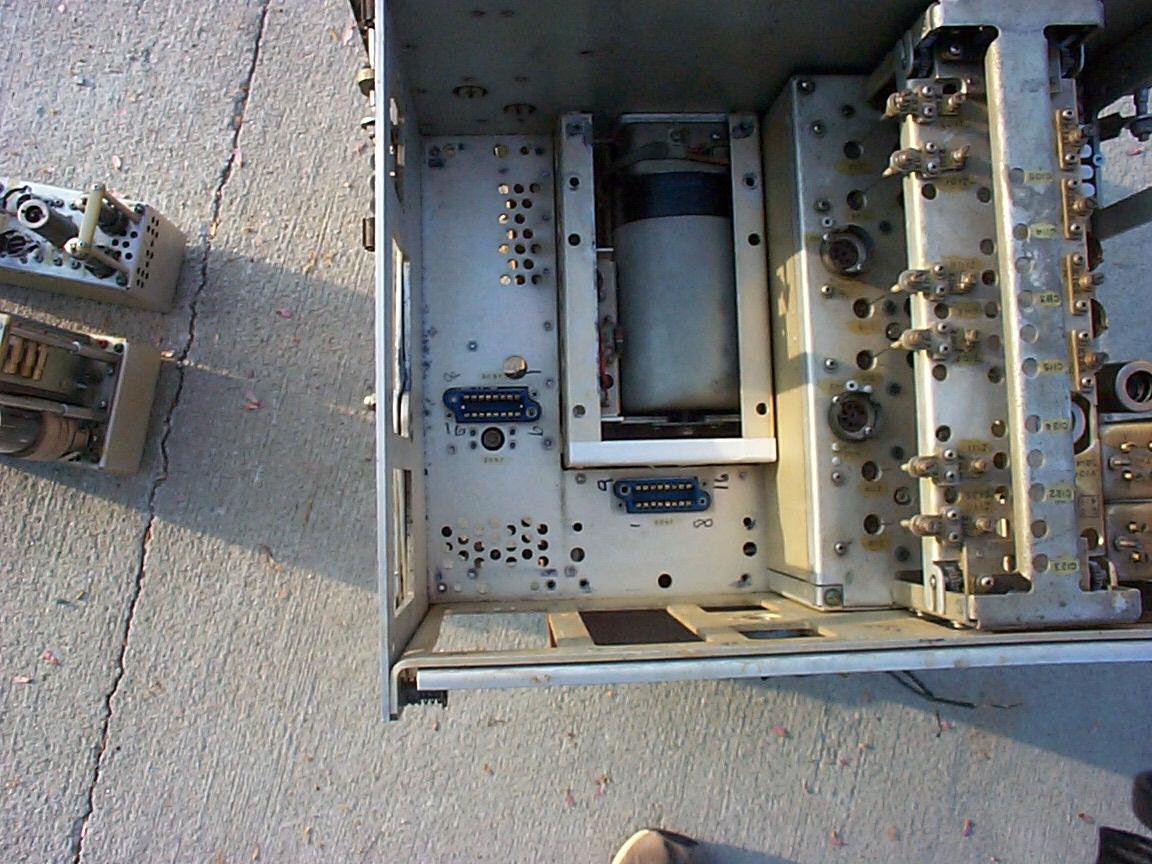
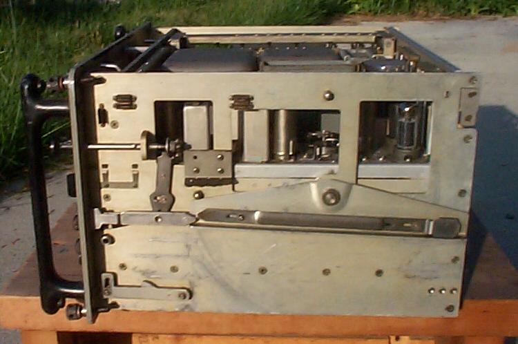
IF/AF and Power supply modules remove quite easily. Below are images of
the partially emptied mainframe, with the PTO showing below the power
supply module location. Also shown are the modules removed.
|
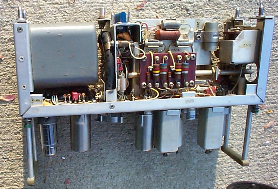
Bottom view
|
|
Left side
|
Right side
|
The PTO is a Collins 70H-10, which tunes from 2.58 - 4.58 Mc. The front panel contains a switch to select the PTO ("MO"), or one of four internal crystals, which in this receiver are at 2.58, 3.58, 4.33, 4.58 Mc. PTO tubes are a pair of 5749's. To the right is a close-up of the PTO nestled in the bottom of the rx. | 
|
| Inside of the IF/AF module. AF uses a pair of 6005's (6AQ5's) in P/P with 600-ohm output. | |||
 |
|
- | - |