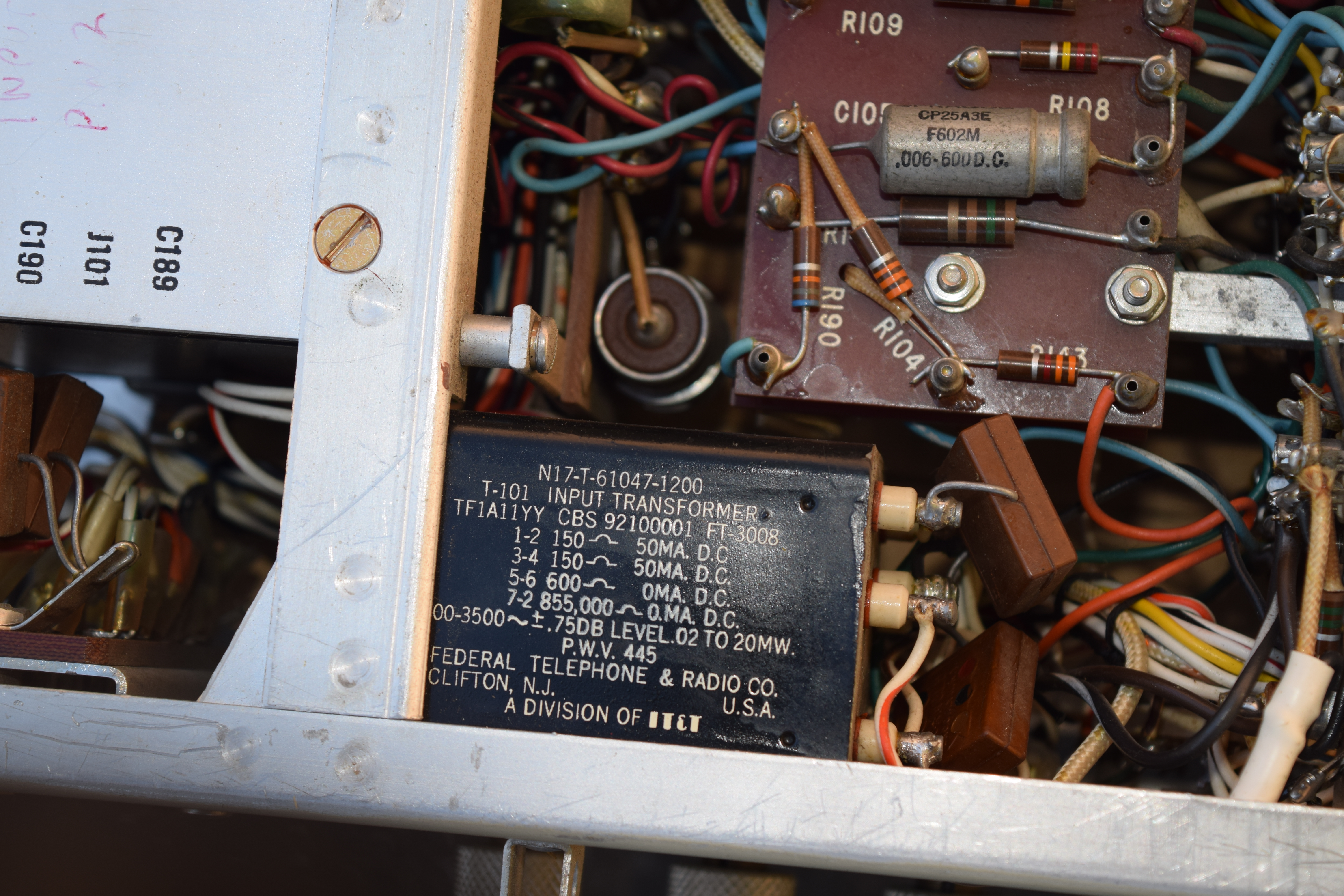
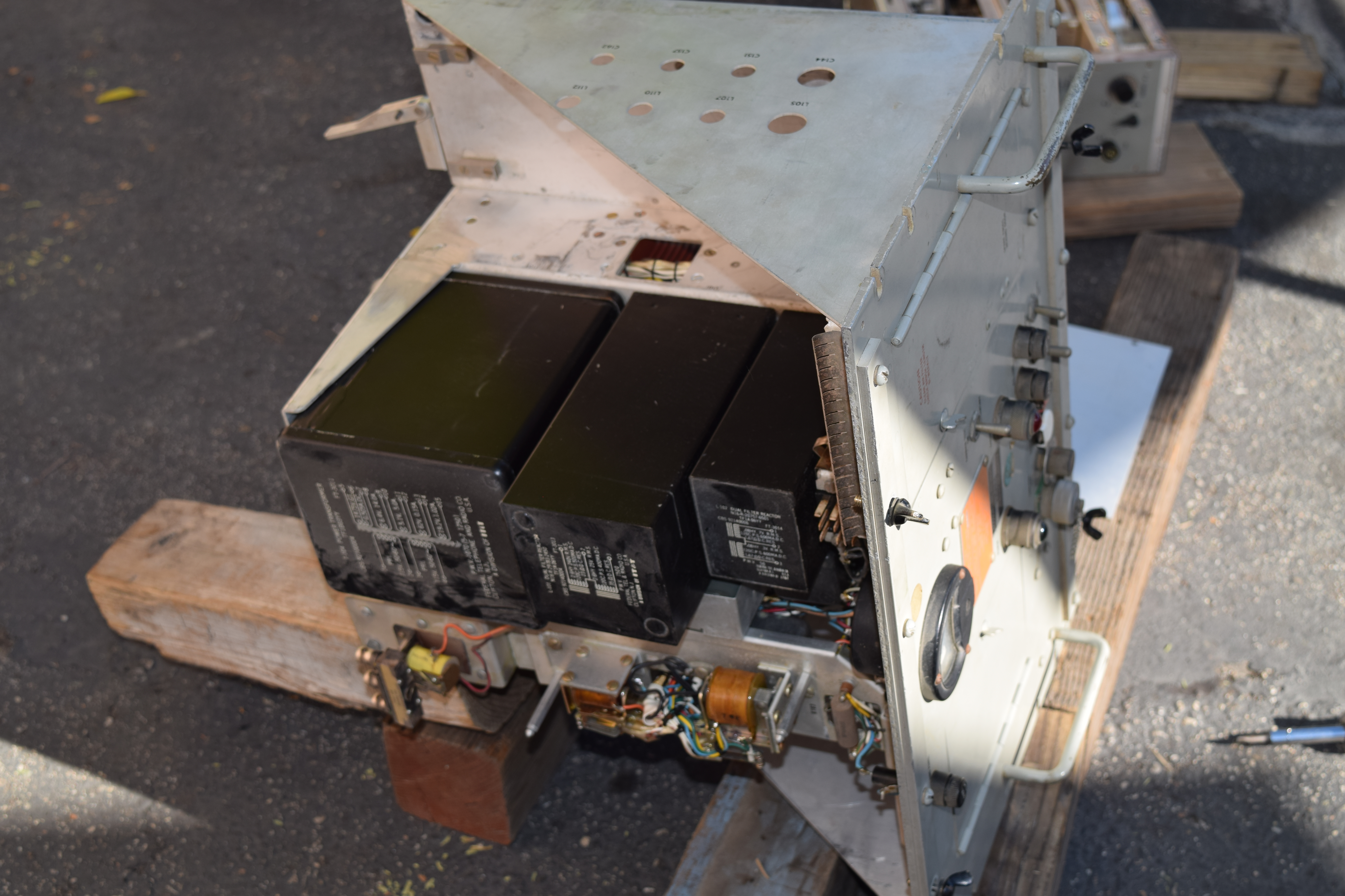
AM-1365/URT UHF Amplifier
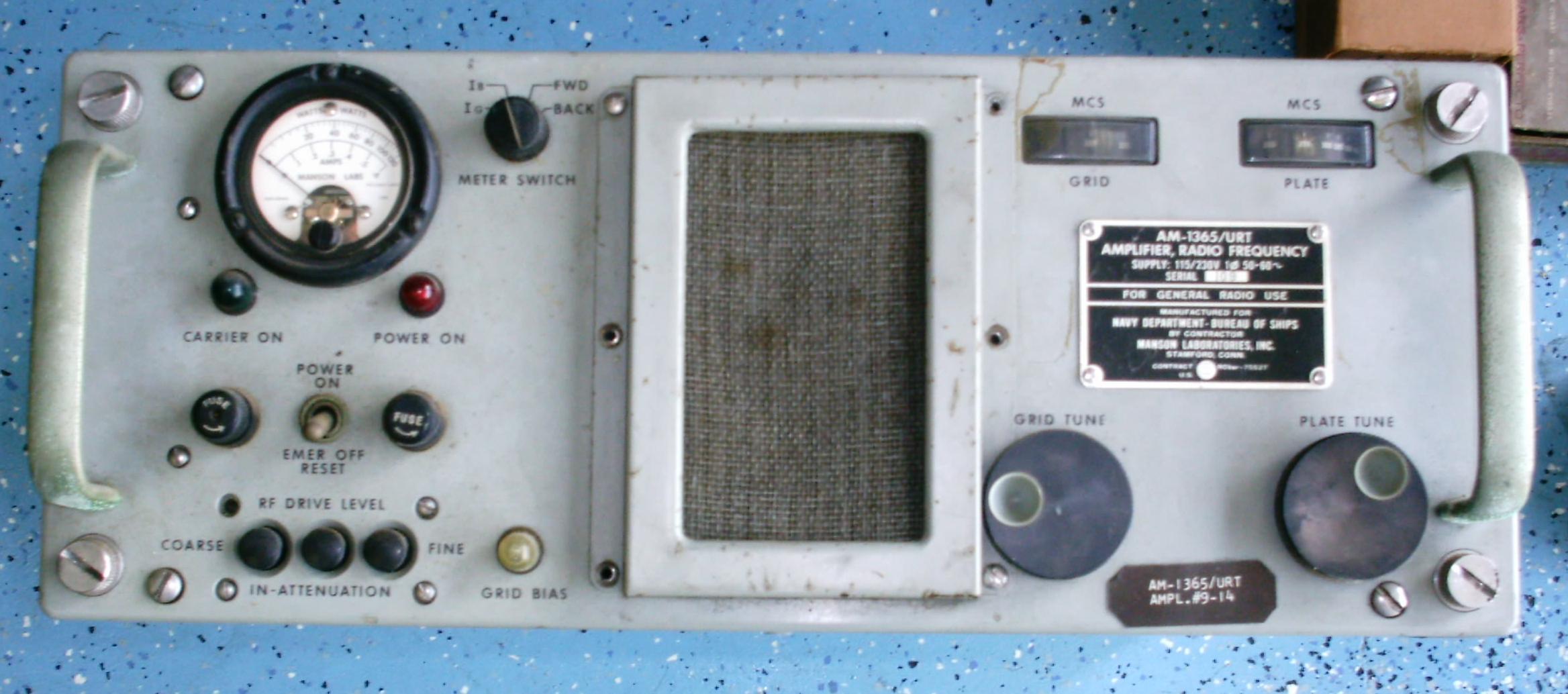
manuf Manson Lab
AN/FRC-63
AN/FRR-55 receiver
AN/FRT-48 transmitter
AN/FRT-48
AN/GRC-27A
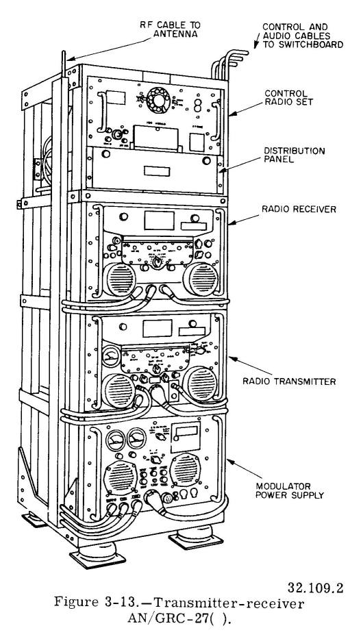
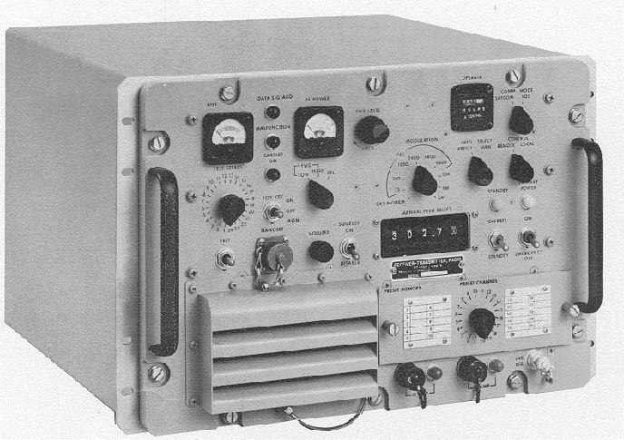
The transmitter normally generates a radio-frequency carrier in a range from 225.0 to 399.9 MHz, with a nominal power output of 100 watts over this range. The transmitter has 3 crystal-controlled oscillators (frequency generators), which employ a total of 38 crystals.
The combination and multiplication (synthesizing) of these 38 crystal frequencies make it possible to produce 1750 frequencies spaced at 100-kHz intervals from 225.0 to 399.9 MHz. Any 10 of these 1750 frequencies can be preset manually by a series of selector switch dials (calibrated in megahertz) in 100-kHz increments. Any 1 of these 10 frequencies (channels) can be selected automatically, either locally or from a remote station. Automatic selection of a preset channel is accomplished in 2 to 7 seconds by a combined autopositioner drive system and a servosystem.
The modulator-power supply provides the transmitter with all necessary operating and control voltages, and supplies amplitude modulation power (either voice or MCW tone) for the transmitter. The transmitter output includes both upper and lower sidebands generated when the carrier is amplitude-modulated.
The receiver normally operates on any 1 of 1750 frequencies, spaced at 1-kHz intervals from 225.0 to 399.9 MHz. The receiver employs a triple conversion superheterodyne system using crystal-controlled oscillators. There are a total of 38 crystals in a synthesizer system. Any 10 channels of the 1750 frequencies can be preset manually. Moreover, any 1 of the 10 channels can be selected automatically, either locally or from a remote station.
Automatic channel selection in the receiver is accomplished by a frequency selector and autopositioner system similar to that in the transmitter. A motor-driven system of gear trains operates the various crystal switches and tuning mechanisms to permit rapid change of operating frequency. Here again, channels are shifted automatically in 2 to 7 seconds.
The receiver is designed for use with directional or omnidirectional antennas having a characteristic impedance of 52 ohms. Audio output circuits for operation of loudspeakers and for operation into telephone lines are built into the receiver. A special output circuit for direction-finding applications is provided also. The receiver is equipped with automatic volume control, automatic noise limiter, and carrier-operated squelch circuits.
The preset channels for the transmitter or the receiver are selected by operating a channel selector switch on the front panel of the respective units or by telephone-type dials on associated radio set control facilities.
The radio set control unit adapts the control circuits of the AN/GRC-27A to the standard 12-wire shipboard remote control system. The control unit provides for the control of power for Radio Set AN/GRC-27A, starting and stopping the modulator-power supply, automatic channel selection in the transmitter and receiver, local or remote control of the transmitter, and squelch adjustment for the receiver.
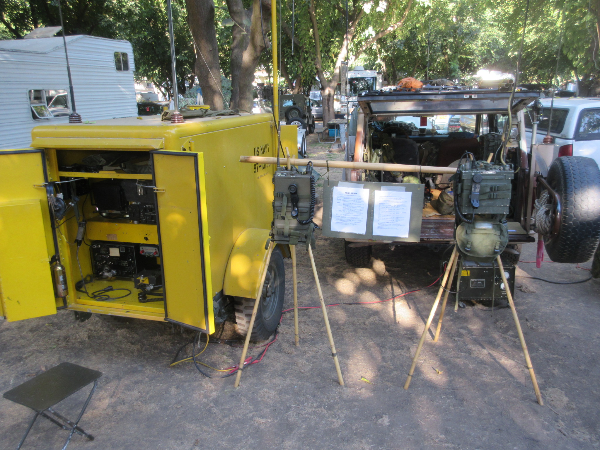
AN/MRC-56 Communications Van
See photos of Andy's trailer at
https://www.qrz.com/db/KD6TKX
- AN/ARC-1 (100-156 mc)
- AN/ARC-27 (225-399.9 mc)
- AN/VRC-32 (30-42 mc)
- TCS transmitter/receiver (HF)
- PU-250/U Generator

AN/PRC-39

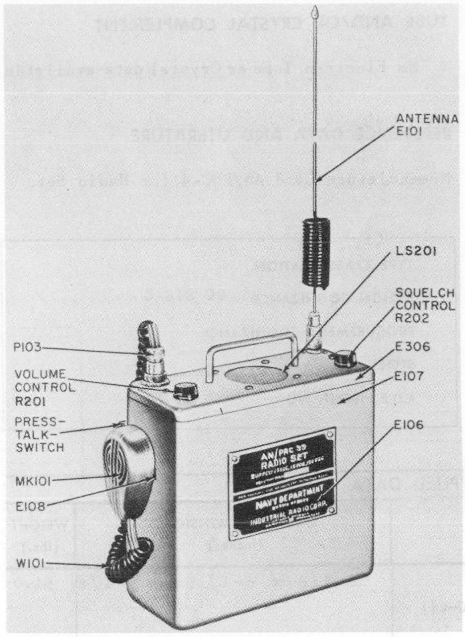
30-42 mc, 1.5w, FM - specs
transistors plus one 1AD4, two 6526
1.5vdc, 15vdc, 150vdc battery
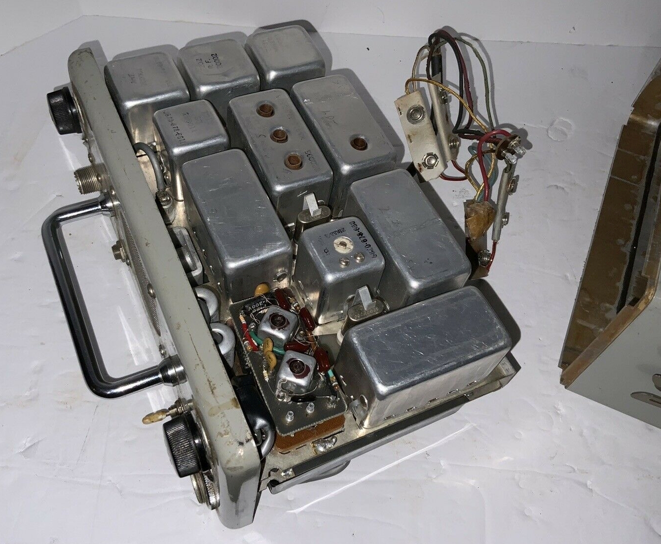
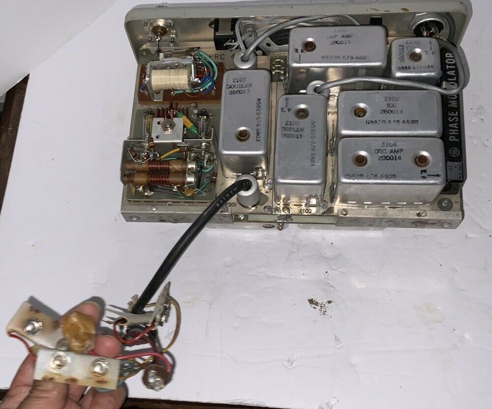
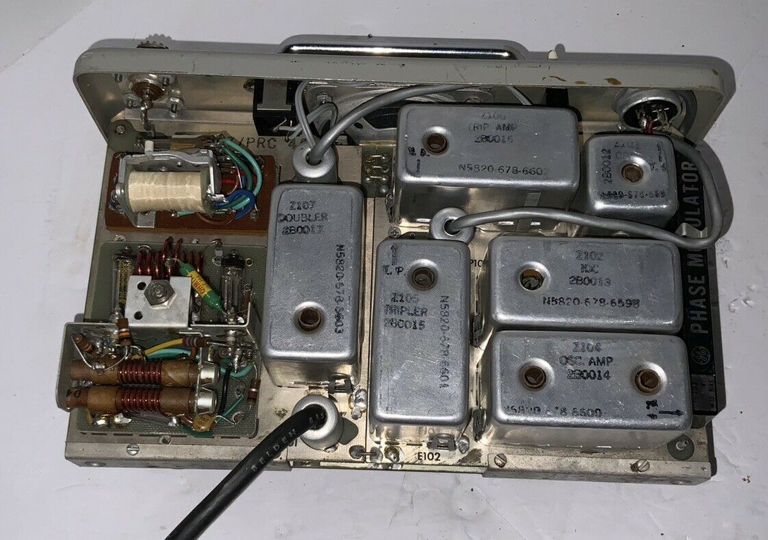
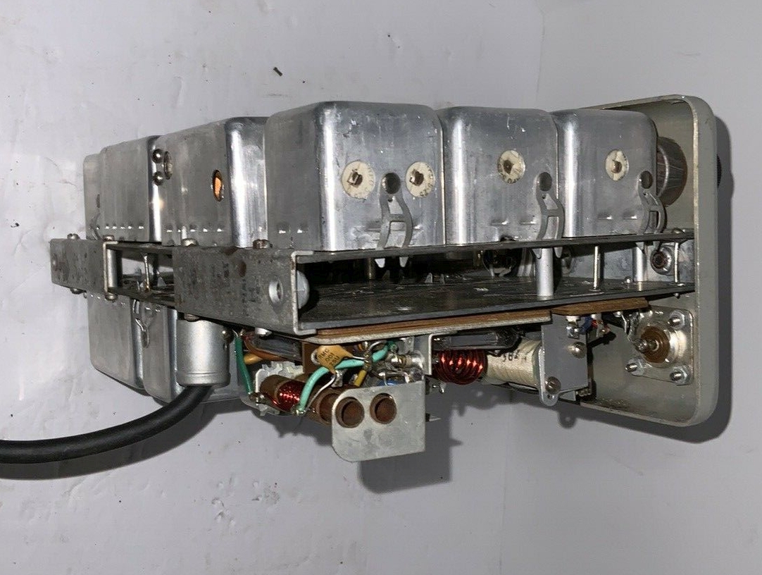
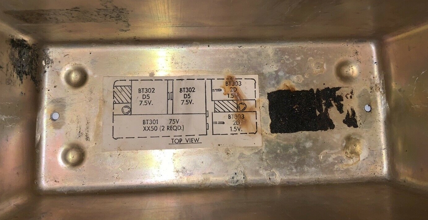
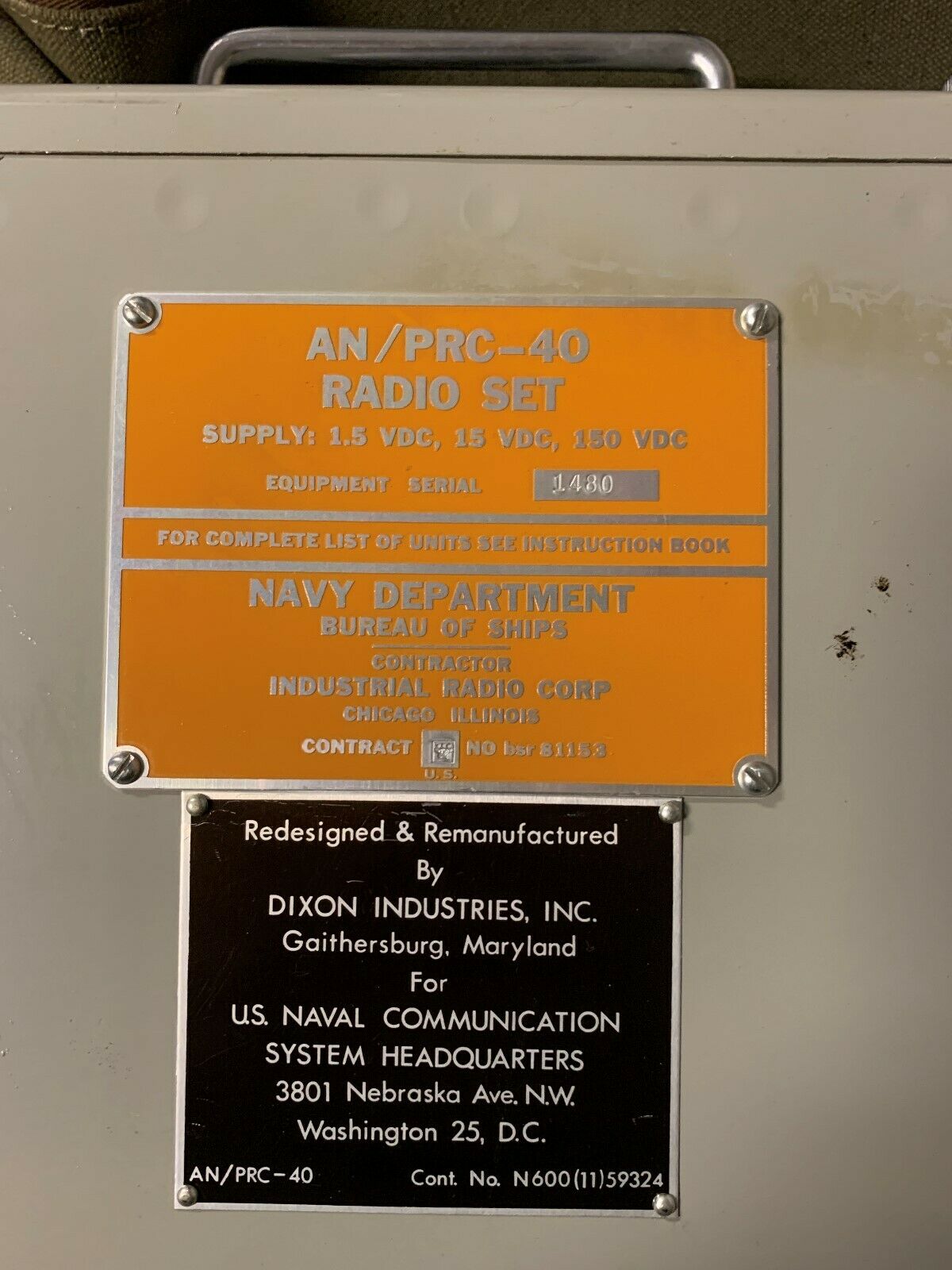
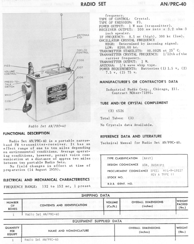
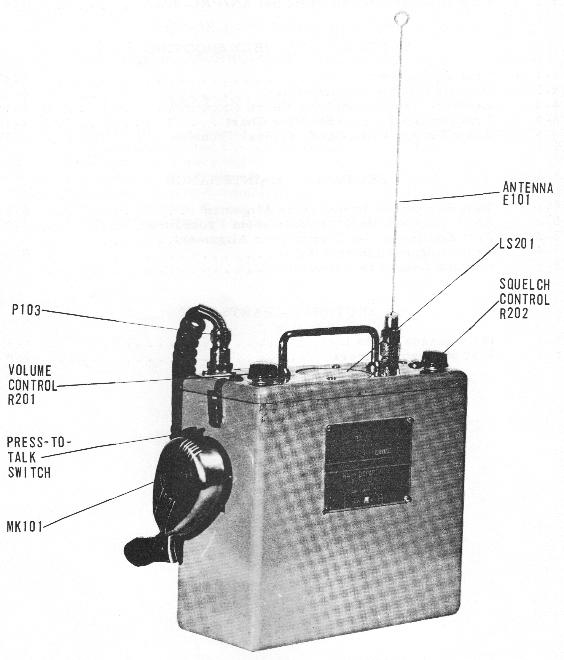
AN/PRC-40
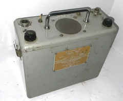
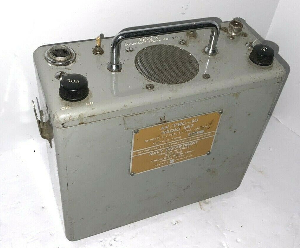
transistors plus three 6526
1.5vdc, 15vdc, 150vdc battery
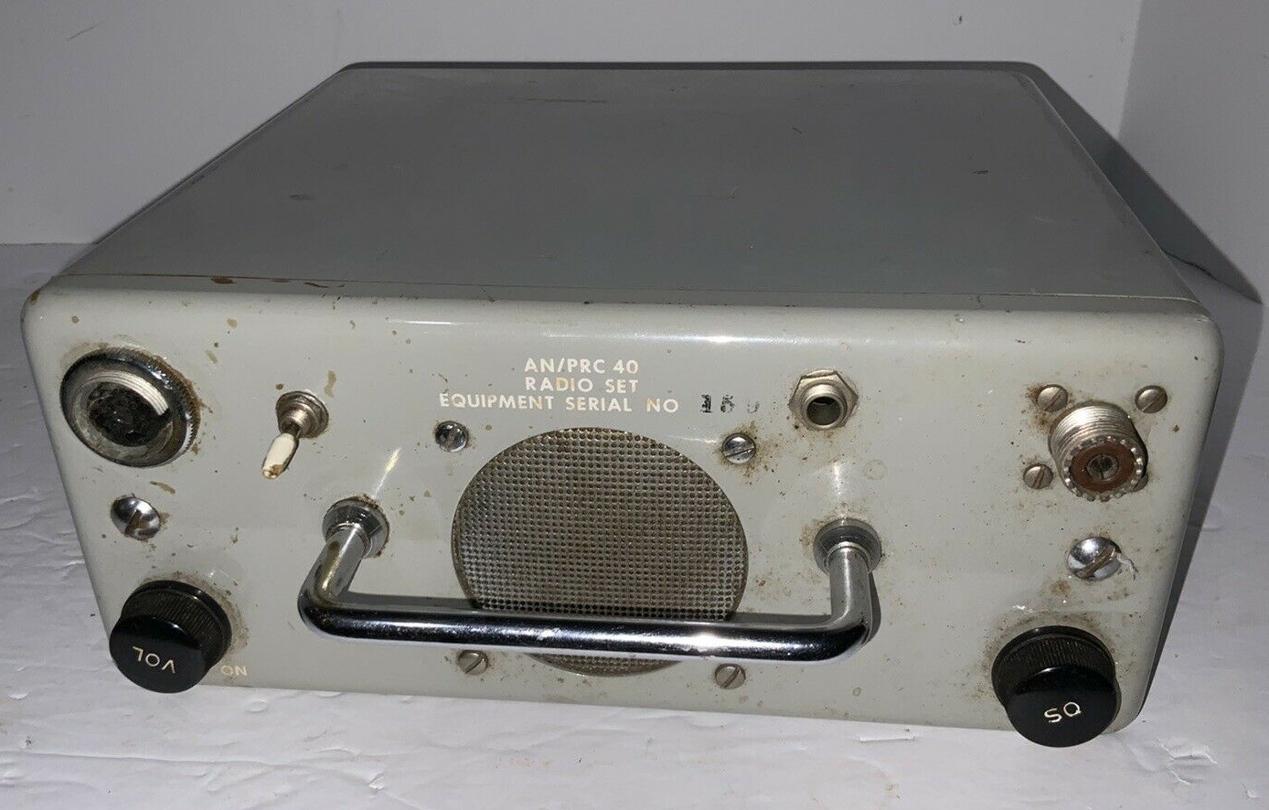
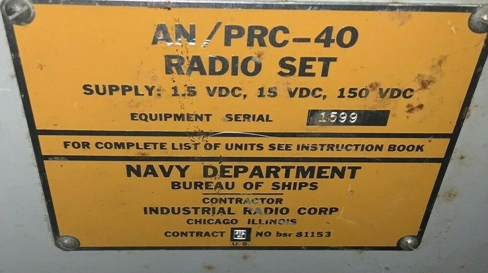
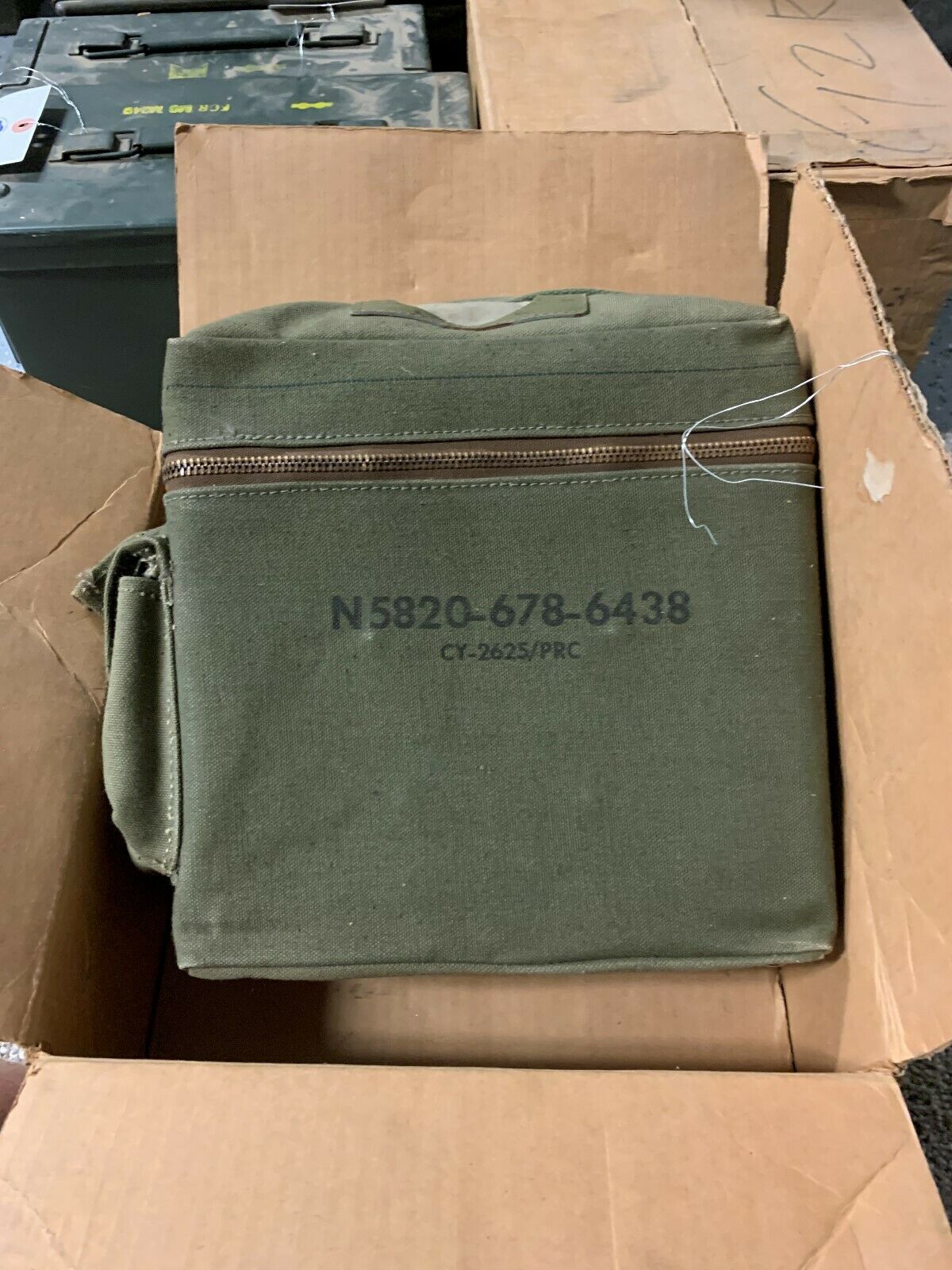
manual - NAVSHIPS 93339
Some (most?) of these were remanufactured to AN/PRC-40AX
- Modification Instructions
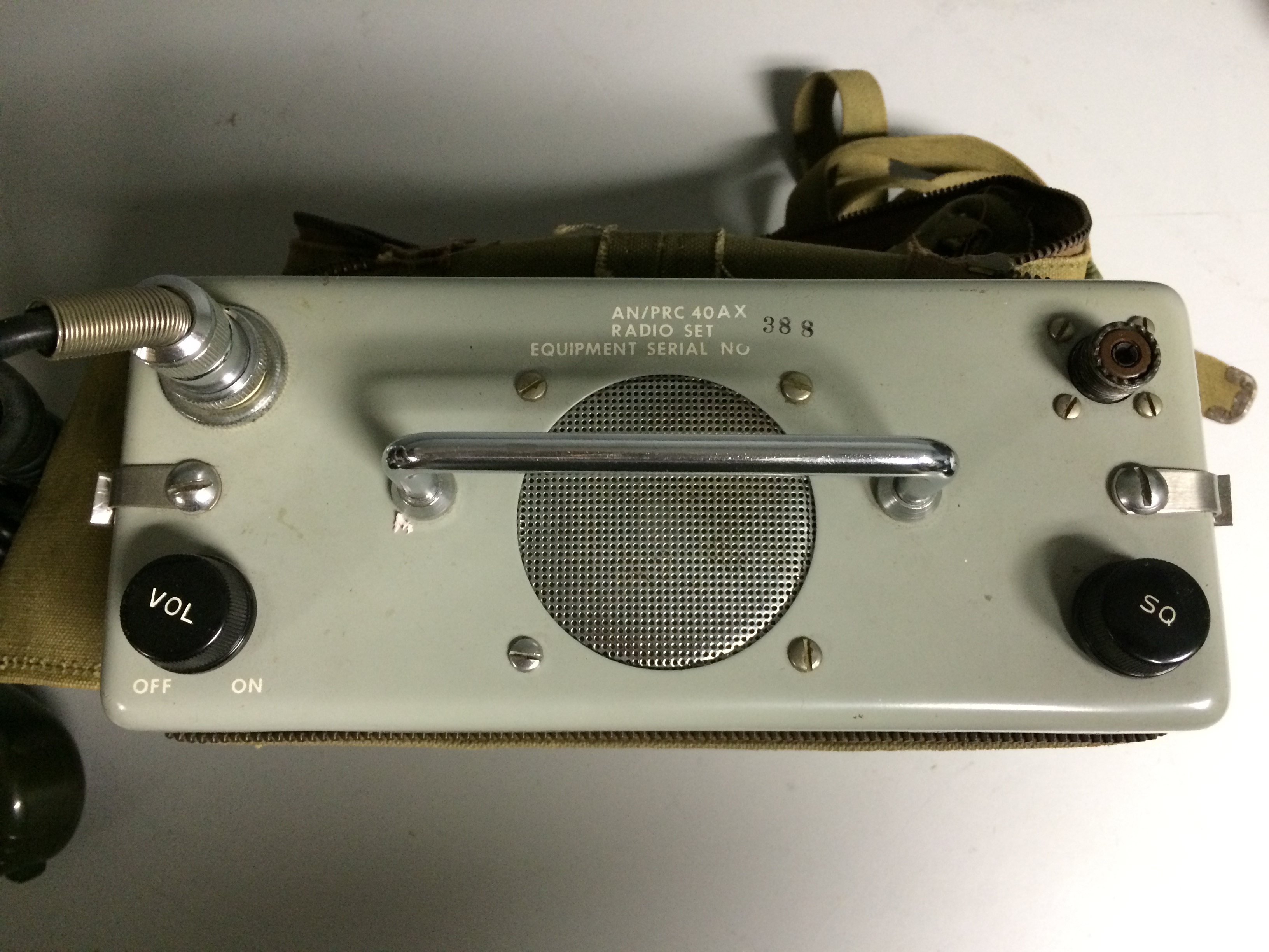
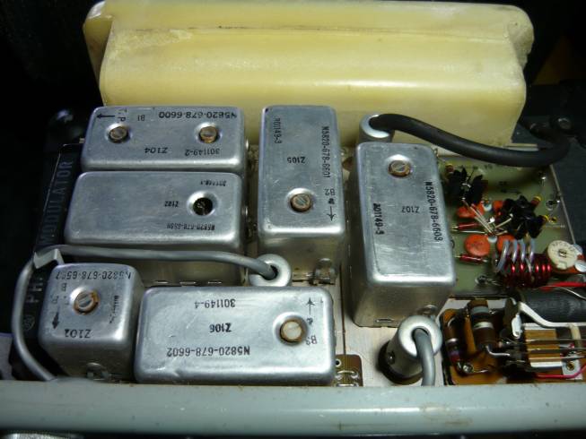
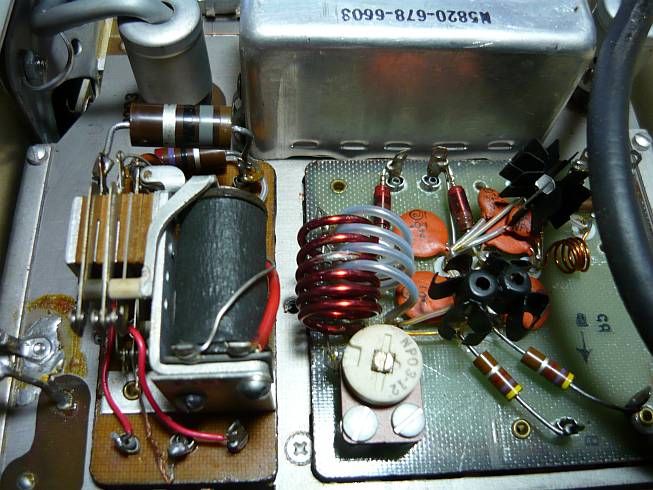
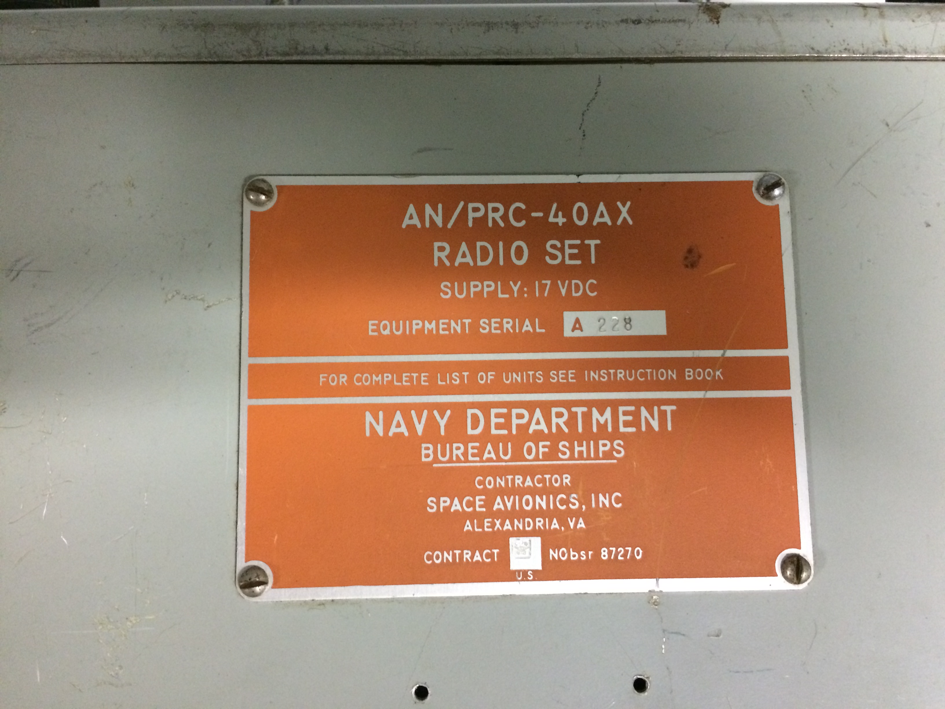
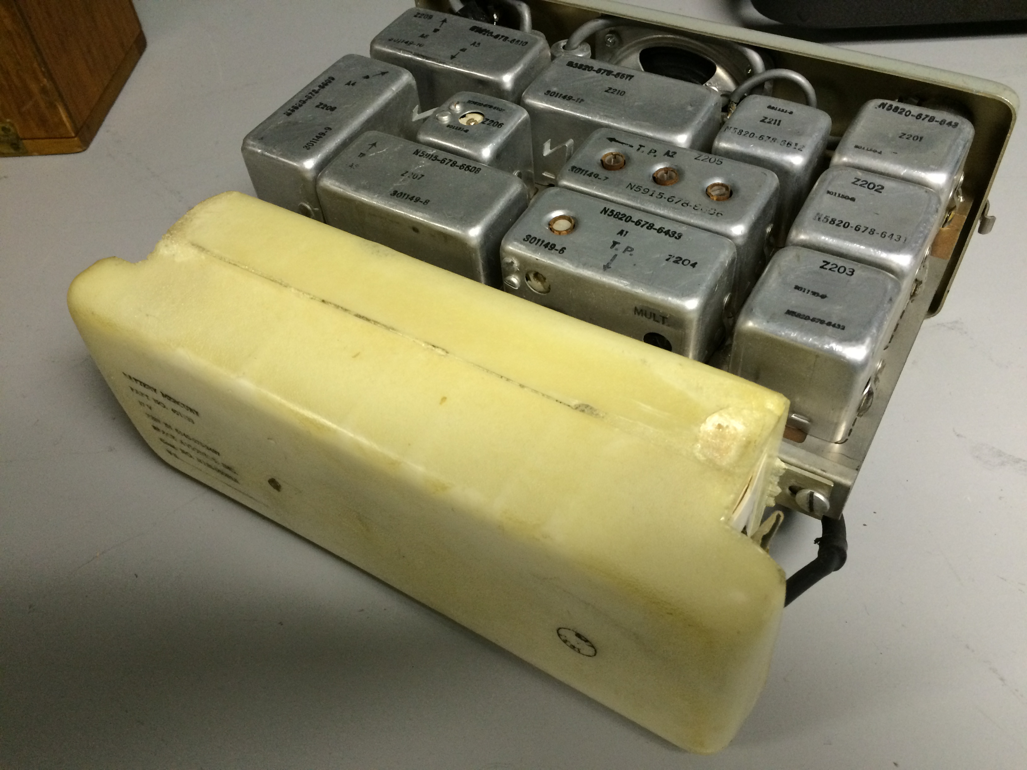
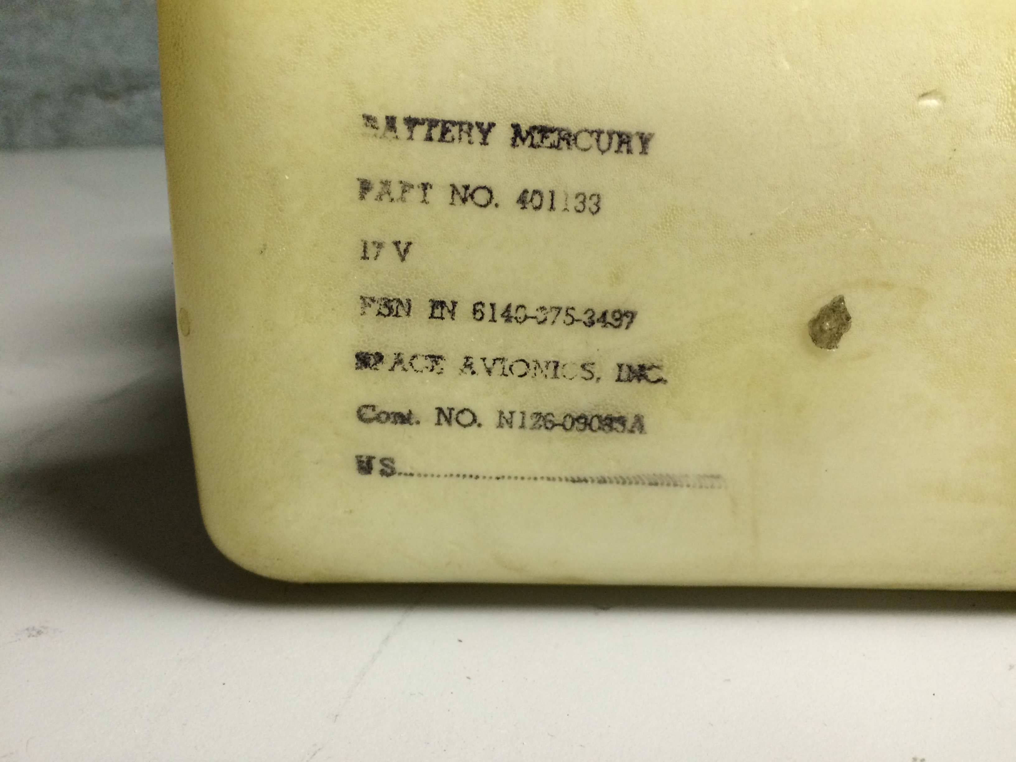
AN/PRC-40AX

This is a fully transistorized remanufacture of the AN/PRC-40.
Uses a 17v mercury battery.
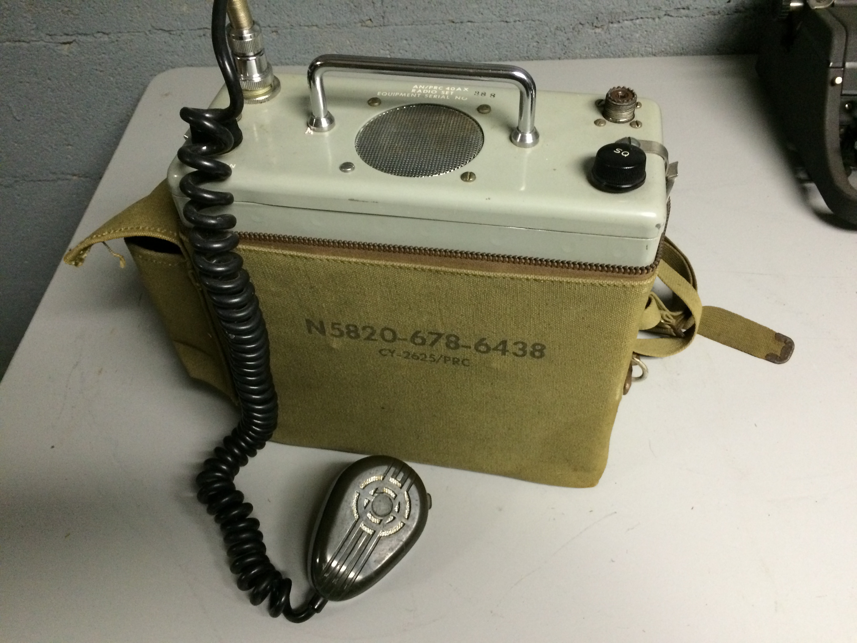
technical manual download
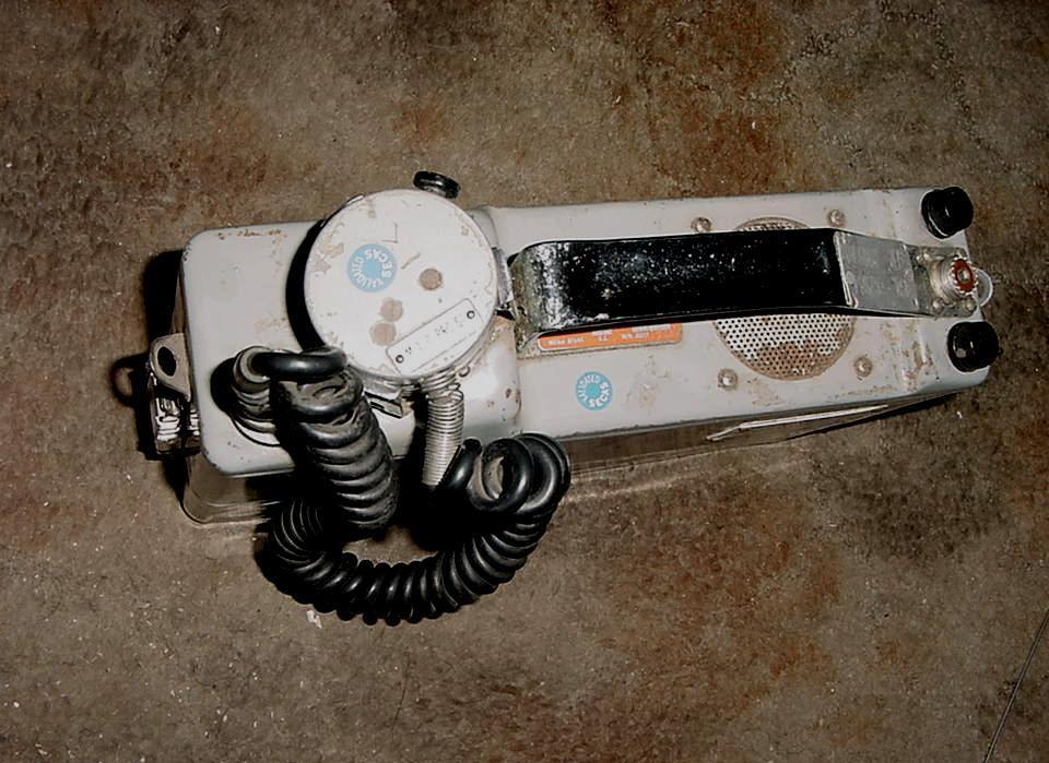
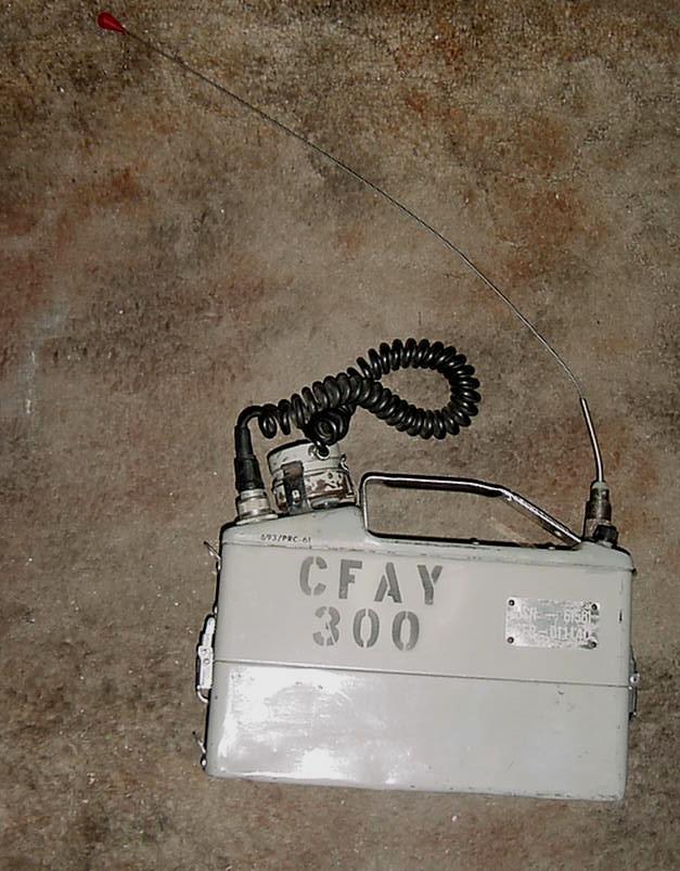
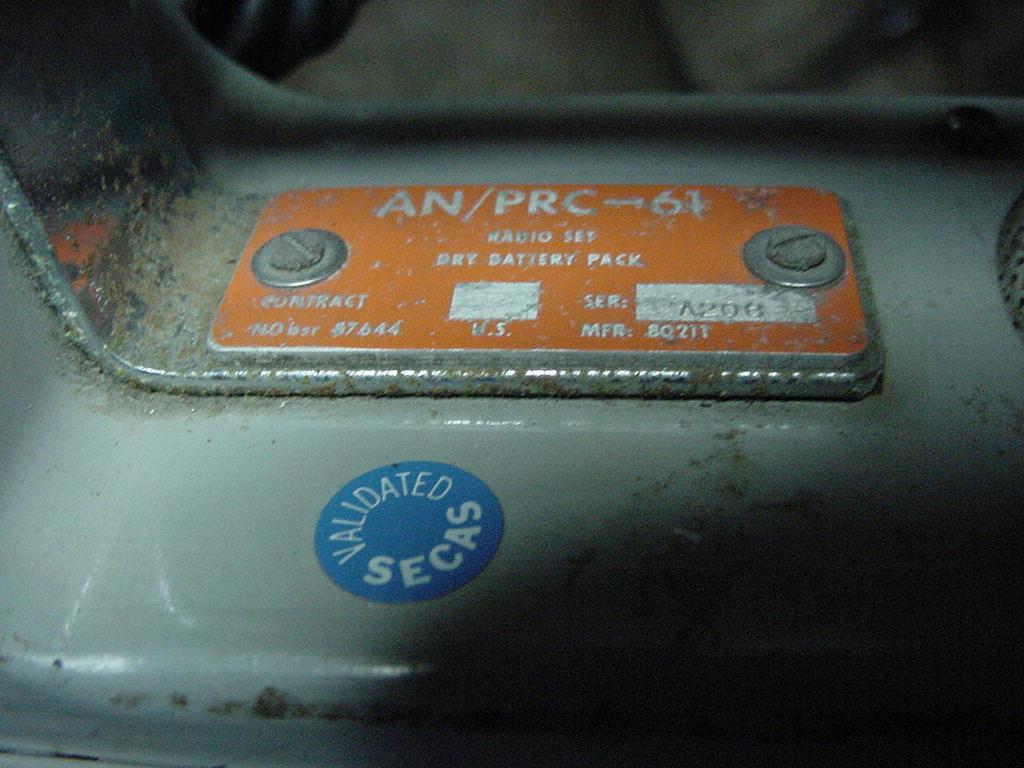
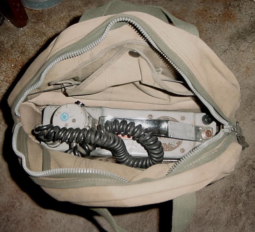
AN/PRC-61

Motorola Z23BAC-1001AM
AN/PRC-73
(REPCO BB-1001-1)
Handheld 1w FM 132-174mc
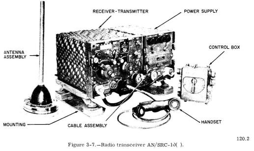
AN/SRC-10( ) - 20-27.9 mc
AN/SRC-13( ) includes R-108/GRC auxiliary receiver
AN/SRC-11( ) - 27-38.9 mc
AN/SRC-14( ) includes R-109/GRC auxiliary receiver
AN/SRC-12( ) - 38-54.9 mc
AN/SRC-15( ) includes R-110/GRC auxiliary receiver
no suffix - 24vdc p/s
X suffix - 12vdc p/s
Y suffix - 115vac p/s
See here for more info
- RT-66/GRC (SRC-10, -13)
- RT-67/GRC (SRC-11, -14)
- RT-68/GRC (SRC-12, -15)
- PP-109/GRC (12vdc p/s)
- PP-112/GRC (24vdc p/s)
- PP-1175A/SR (115vac p/s)
- MX-1583/SRC (dc p/s remote control adapter)
- MX-1986/SRC (ac p/s remote control adapter)
- MT-299/GR mounting for SRC-10, -11, -12
- MT-327/GR mounting for SRC-13, -14, -15
AN/SRC-17 UHF Transceiver
need photo
1kw 225-400mc FSK & FM
Manson Labs (div of Hallicrafters)
NAVSHIPS 94127
AN/URC-9
AN/SRC-20
AN/SRC-21
UHF Transceiver
AN/SRC-20
More photos & info

AN/SRC-21
225-400 mc AM
manuf Collins
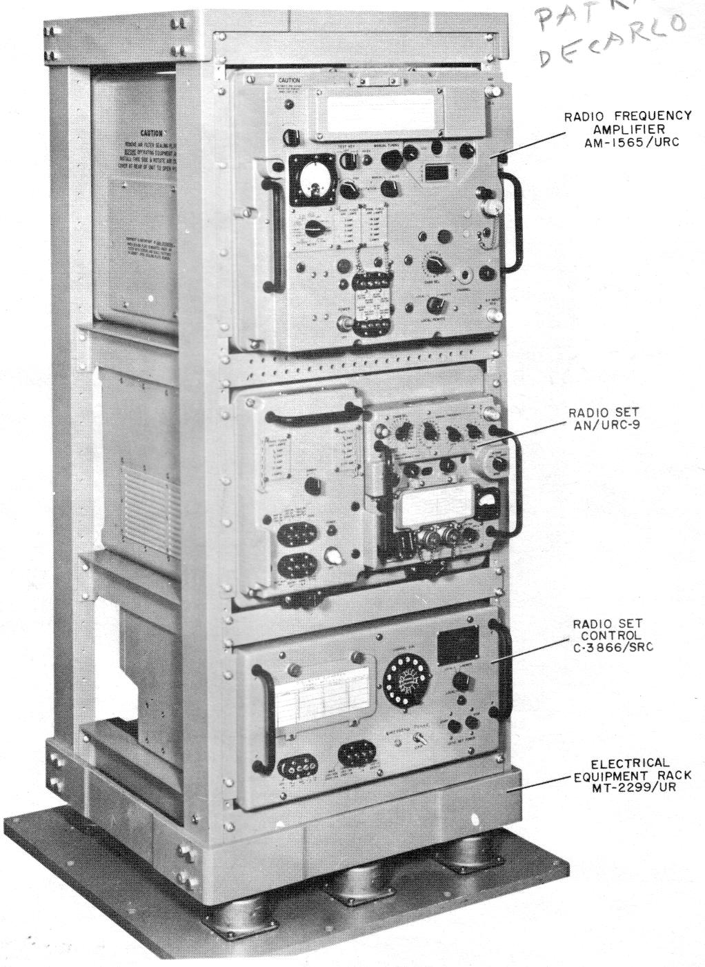
AN/SRC-20 (100 watts)
AM-1565/URC amplifier
AN/URC-9 transceiver
RT-581/URC-9
PP-2702/URC-9)
C-3866/SRC control
AN/SRC-21 (16 watts)
AN/URC-9 transceiver
RT-581/URC-9
PP-2702/URC-9
C-3866/SRC control
"A" version has 0.05mc channel spacing, "non-A" has 0.1mc channel spacing.
More photos & info
NAVSHIPS 0967-032-5000
NAVSHIPS 0967-125-6000
NAVSHIPS 0967-378-2000
NAVSHIPS 0967-438-9000
Contact www.wa5cab.com for copies of the manuals above
AN/SRC-20 and AN/SRC-21
C School Trainee's Guide 1967
NAVPERS 93402-1 Information Sheets
NAVPERS 93402-2 ?
NAVPERS 93402-3 Schematics
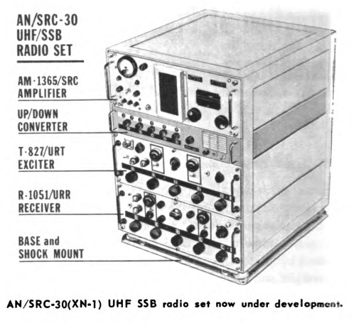
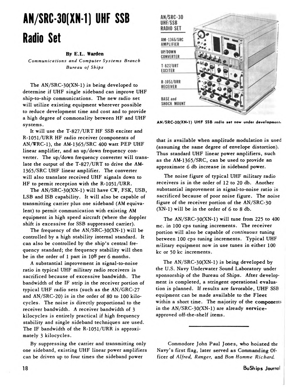
UHF SSB transceiver based on R-1051 and T-827
AN/SRC-31 NTDS Transceiver


225-400 mc, 0.05mc channel spacing
300w AM, 1500w CW/FSK
Electronic Communications, Inc. (division of NCR)
The AN/SRC-31 radio set, which with certain modifications is designated as the AN/SRC-31A and B, was developed as a shipboard system to provide the UHF functions required for inter-ship subsystems communications of the Naval Tactical Data System (NTDS). It is a miniaturized, modular, solid state transceiver operating in the 225-400 MHz range, capable of AM, FM and frequency shift keying (FSK) transmission, and is automatically tunable to 3500 channels in 50 kHz increments. Ten pre-set channels may be locally or remotely selected.AN/URC-16( ) - 20-27.9 mc
AN/URC-17( ) - 27-38.9 mc
AN/URC-18( ) - 38-54.9 mc
no suffix - 24vdc p/s
X suffix - 12vdc p/s
Y suffix - battery and hand-cranked generator
AN/URC-20 - 20-27.9 mc
AN/URC-21 - 27-38.9 mc
AN/URC-22 - 38-54.9 mc
AN/URC-80(V)

AN/URC-85
3-2 RADIO SET GROUP.
Radio Set AN/URC-85 is a two-channel, full duplex (or simplex) UHF radio transceiver
for data and voice communications in the 225.00 to 399.95 Mhz frequency
band. Electrical Equipment Cabinet CY-7403/URC-85 contains two full-duplex
AN/URC-82A UHF transceivers, four radio set controls (C-9059/UR), an indicator panel (ID-1953/UR), a local control panel, a 1 kW linear power amplifier (AM-6520/UR), and its
high-voltage power supply (PP-6799/UR).
3-2.1 Each of the 3500-channel AN/URC-82A transceivers is capable of independent
operation , allowing use in a multi-mode configuration. These modes consist of
AM (amplitude modulation), FM (frequency modulation), and FSK (frequency shift
keying), each of which is available in a duplex or simplex frequency capability.
Transmitter power output to the antenna filter group is 100 watts for the FM
and FSK modes of operation , and 30 watts for the AM mode. The linear RF power
amplifier can be utilized with either transmit channel to increase a selected
channel power output to the antenna filter group to 1000 watts for the FM and FSK
modes, or 250 watts for the AM mode.
3-2.2 The local control panel In Electrical Equipment Cabinet CY-7403/URC-85 is equipped with two handset jacks that may be used for orderwlre, local voice
communications, or test purposes.
3-3 ANTENNA FILTER GROUP.
Electrical Equipment Cabinet CY-7404/URC-85 contains two UHF multiplexers: Multiplexer
TD-1118/UR, which consists of two Bandpass Filters F-1332/UR and a combining
network, is used for receive; and Multiplexer TD-1117/UR, which consists of two 1000-watt Bandpass Filters F-1396/UR and a combining network , is used for transmit. The
antenna filter group functions as an impedance matching and combining network between
the UHF transceivers of the radio set group and the transmit and receive antennas.
Both multiplexers are automatically tuned when the associated receiver or transmitter frequency is selected.
3-4 REMOTE CONTROL GROUP.
The optional remote control group consists of a control panel and four Radio Set Controls C-9059/UR. All modes of operation except local handset may be
controlled by the remote control group.
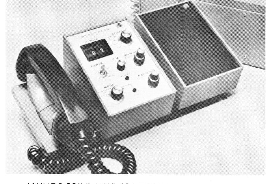
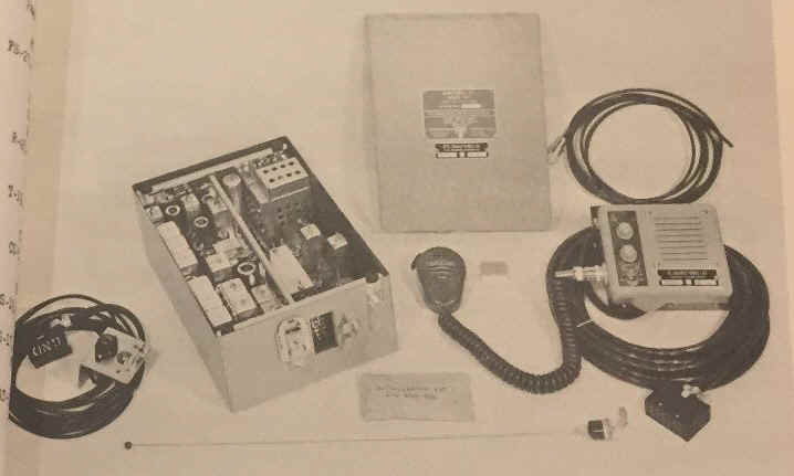
AN/URT-7
AN/URT-7A
AN/URT-7B
AN/URT-7C
Transmitter
two 4x150A finals, 30w output
xtal controlled - 4 channels
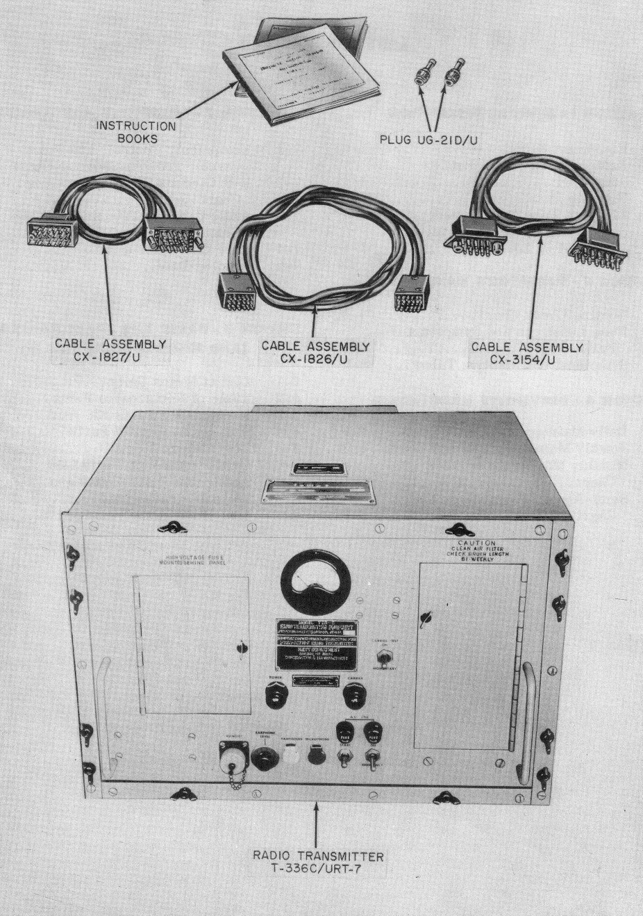
Transmitter T-336/URT-7 including
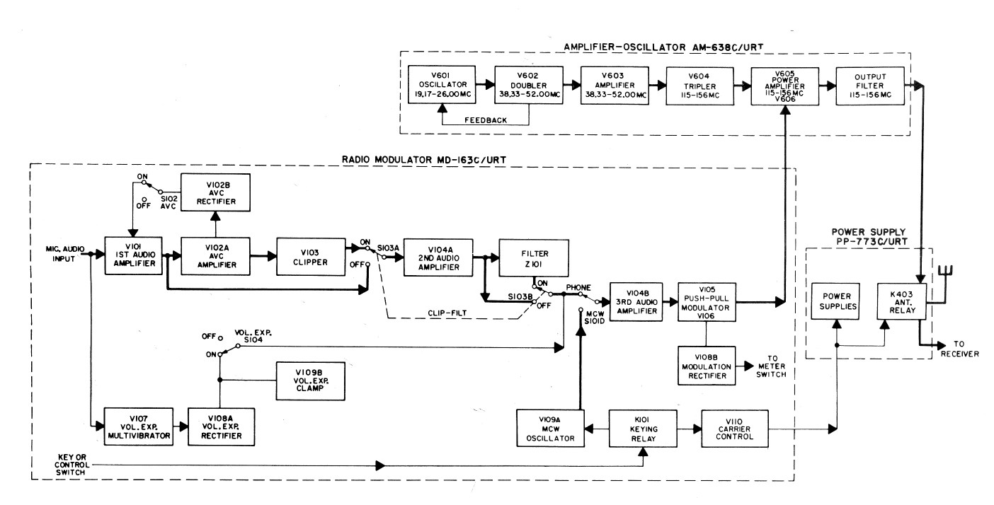
- Amp/Osc AM-638/URT
- Modulator MD-163/URT
- Power Supply PP-773/URT
manuf URT-7C Rauland-Borg 1956
- Photo - URT-7 & accessories
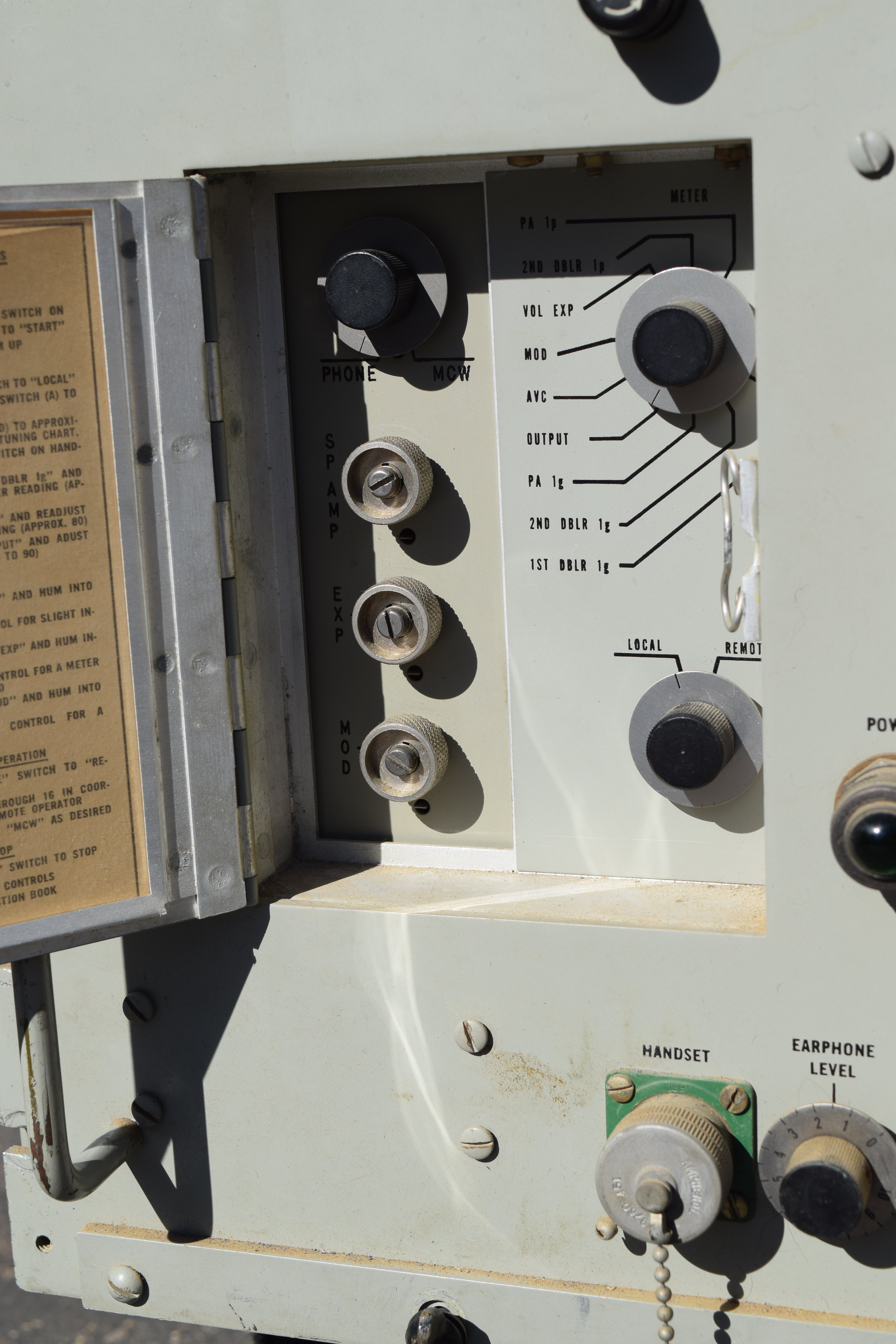
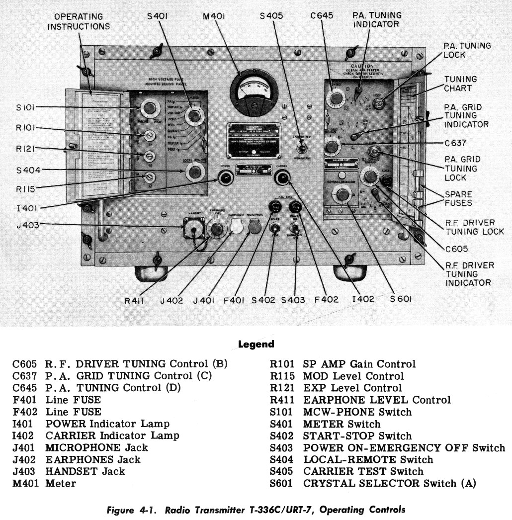
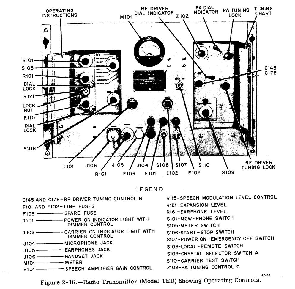
- Photo - Controls
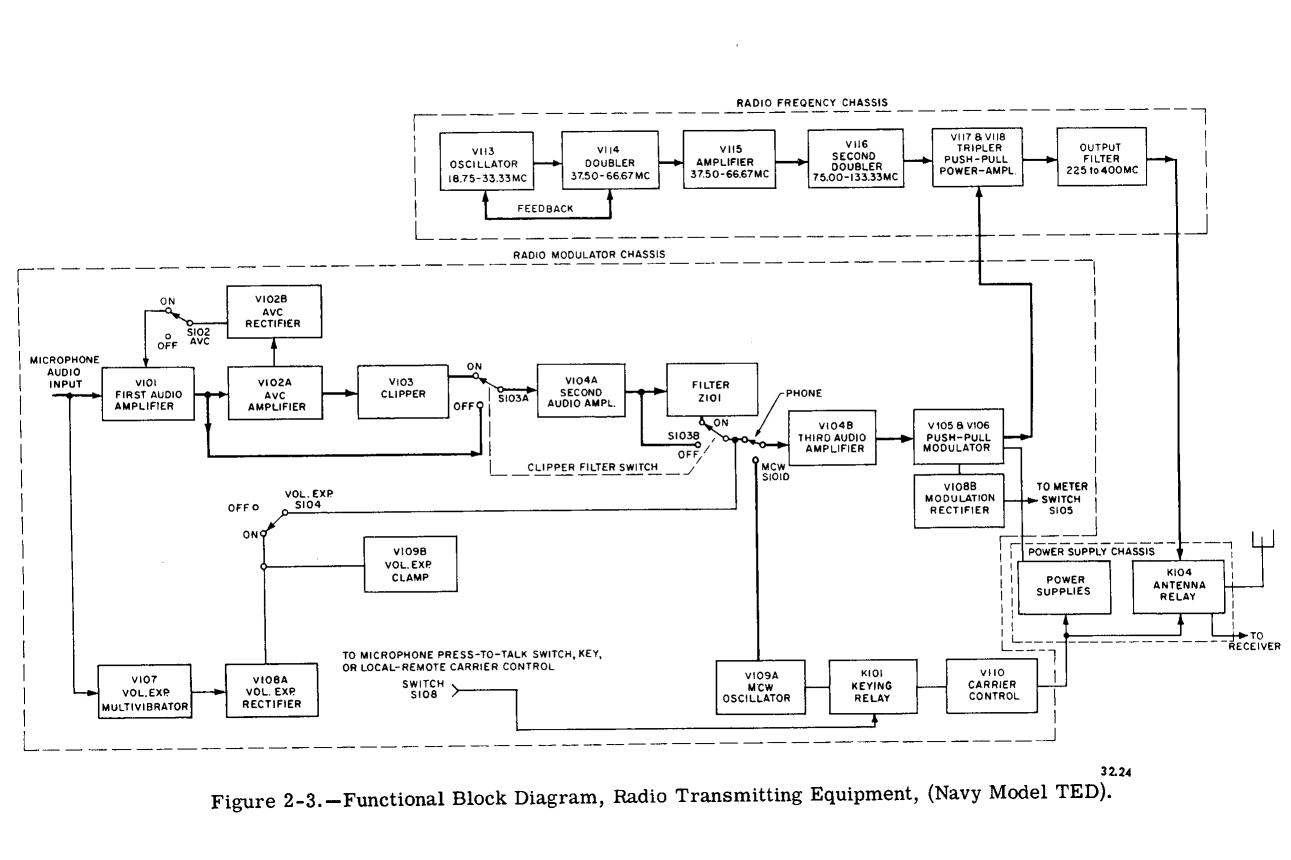
- Figure - Block Diagram
- NAVSHIPS 91684 (URT-7)
- NAVSHIPS 92832 (URT-7C)
manual pdf
Similar to TED, but VHF
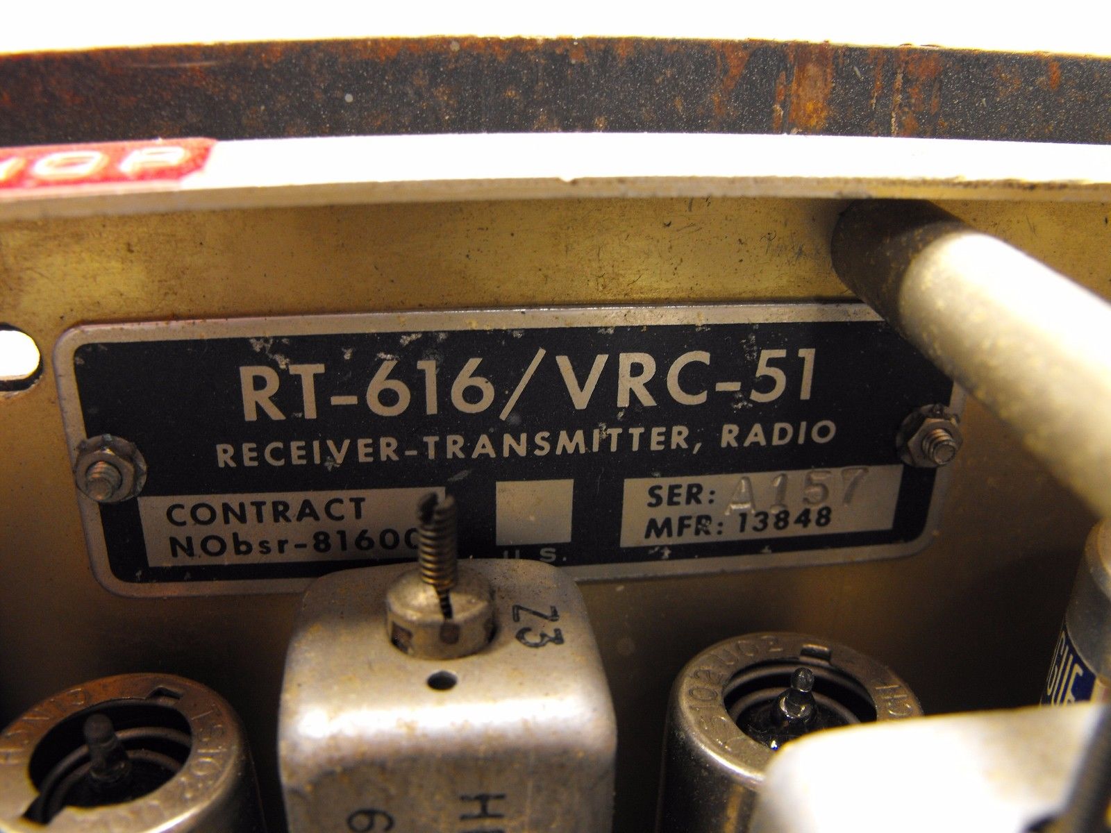
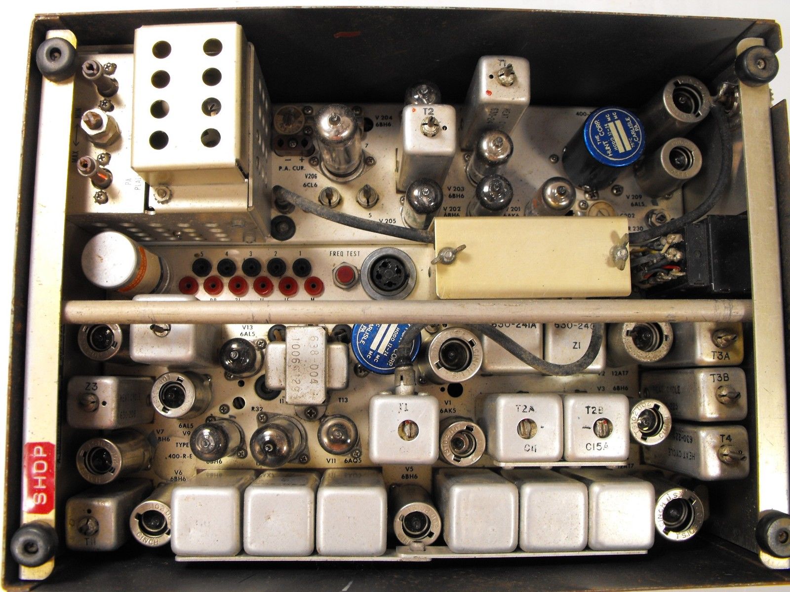
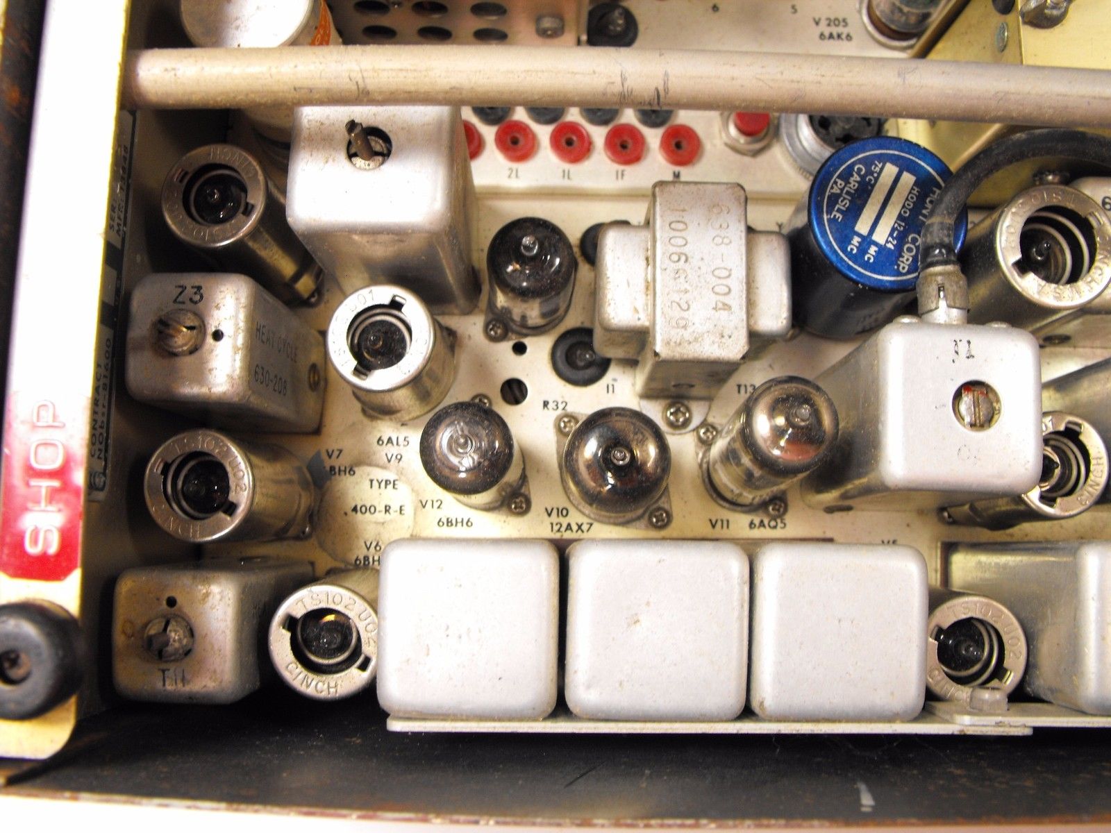
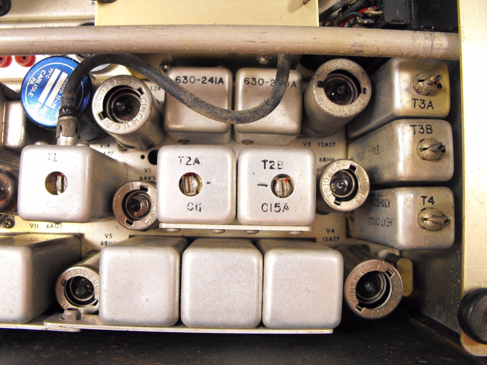
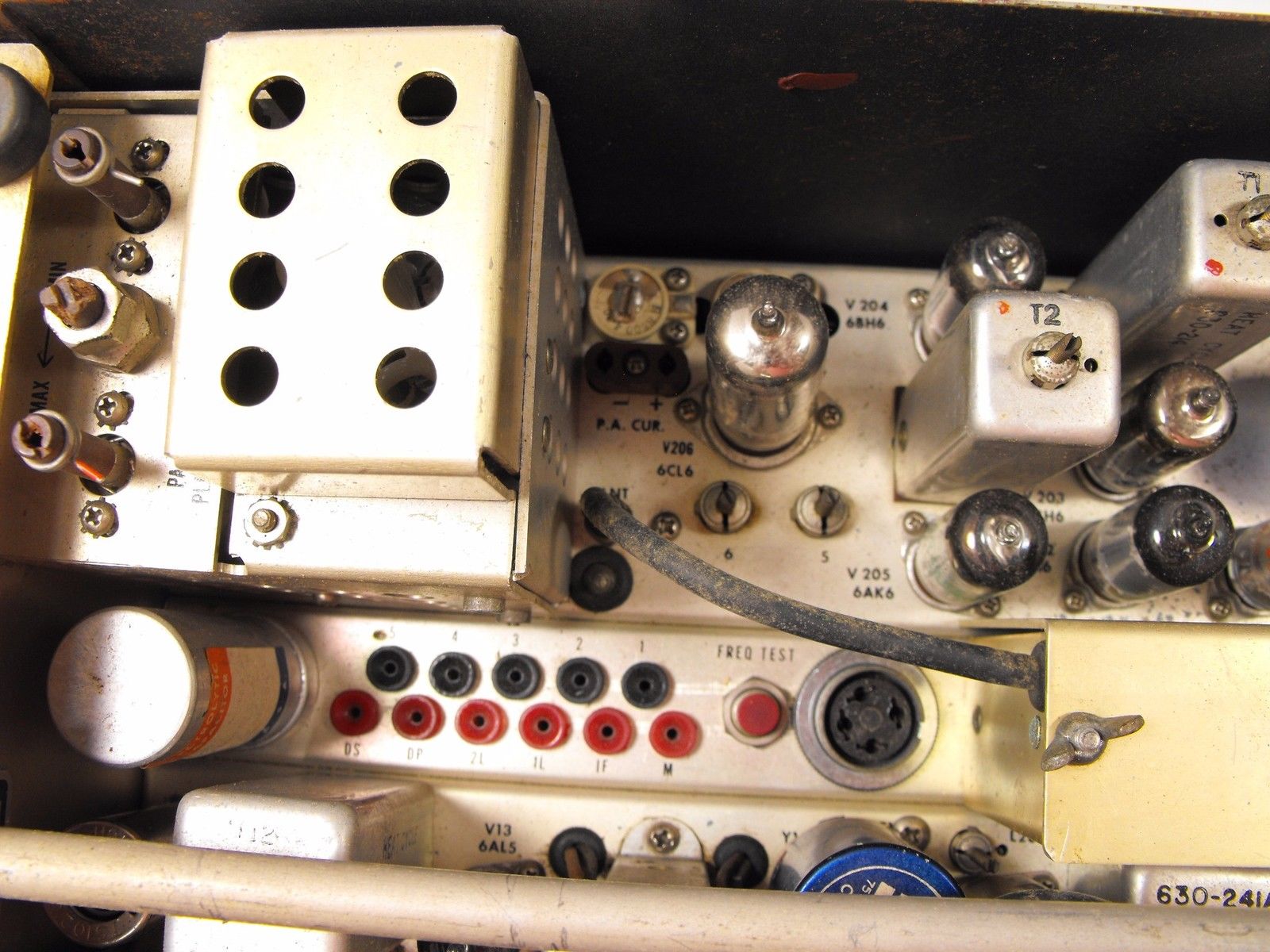
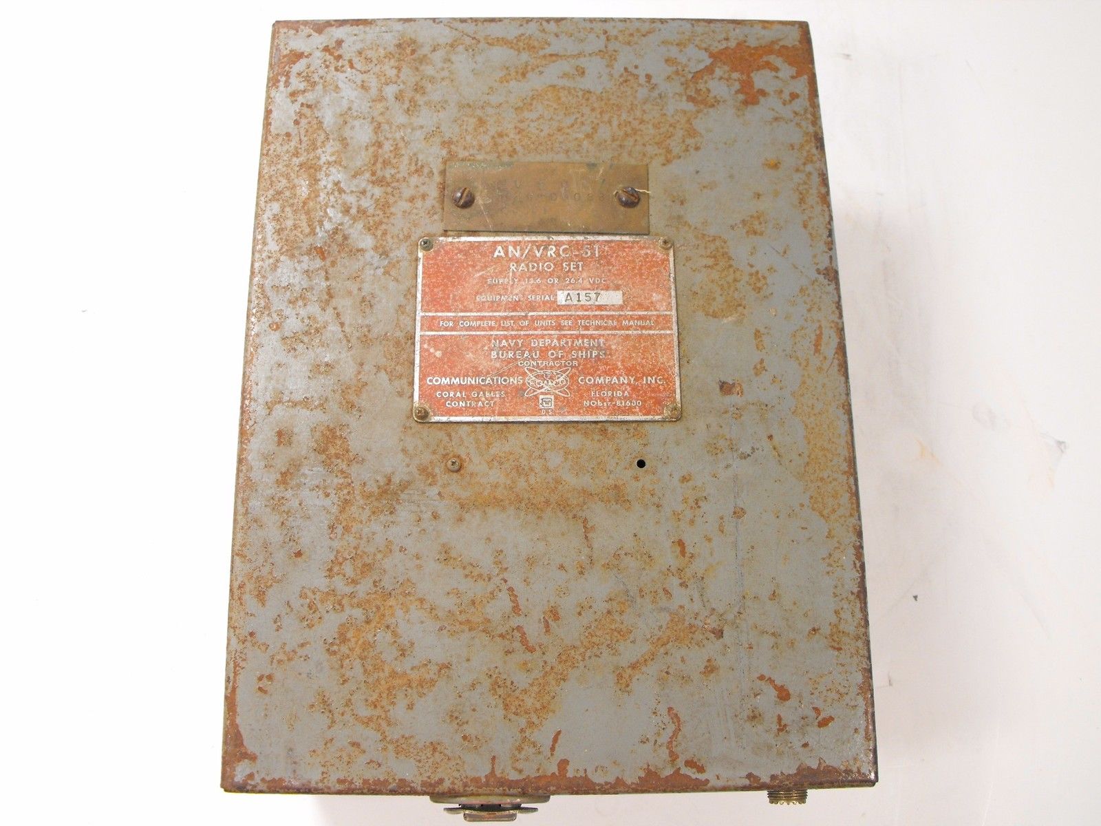
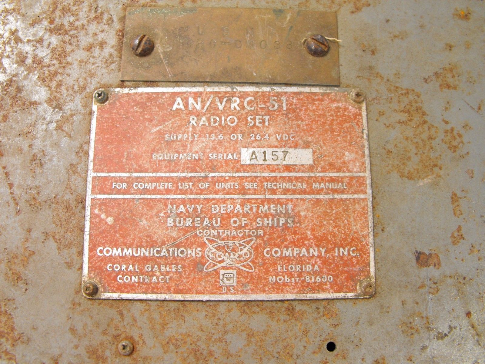
AN/VRC-51 (RT-616/VRC-51)
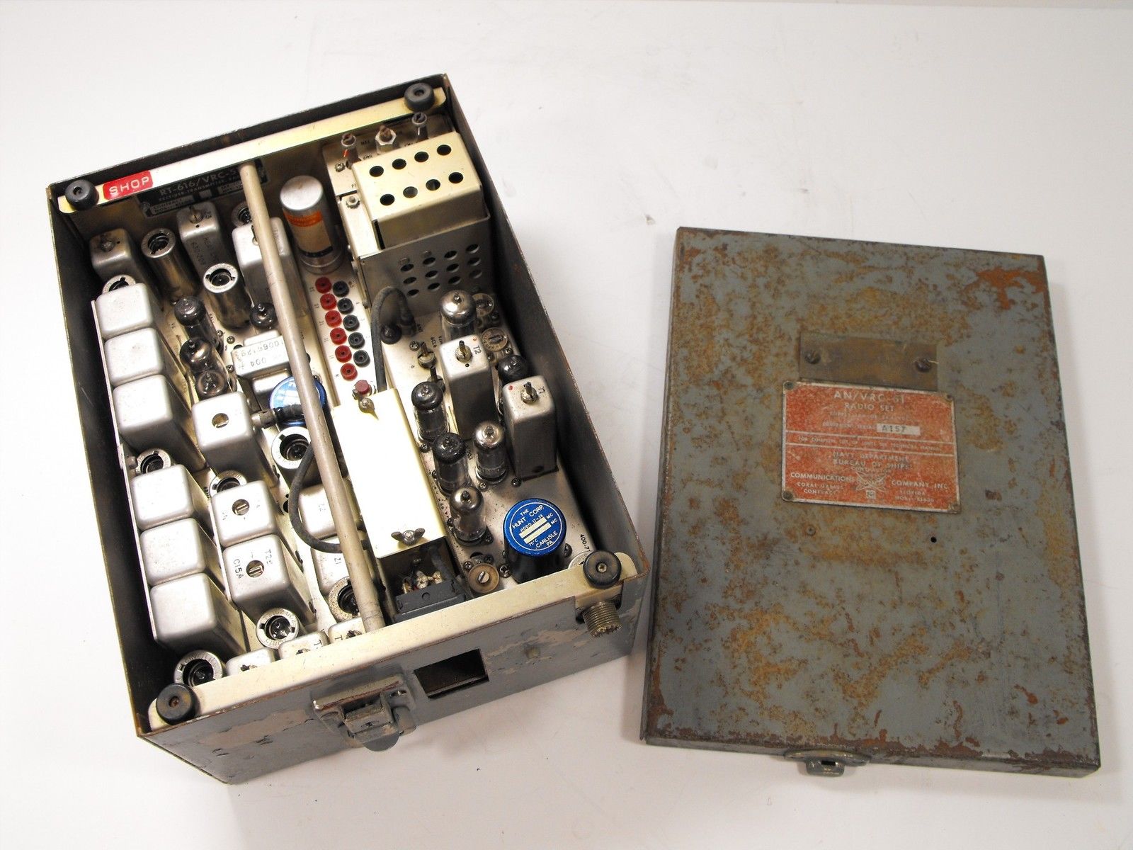
12vdc or 24vdc operation


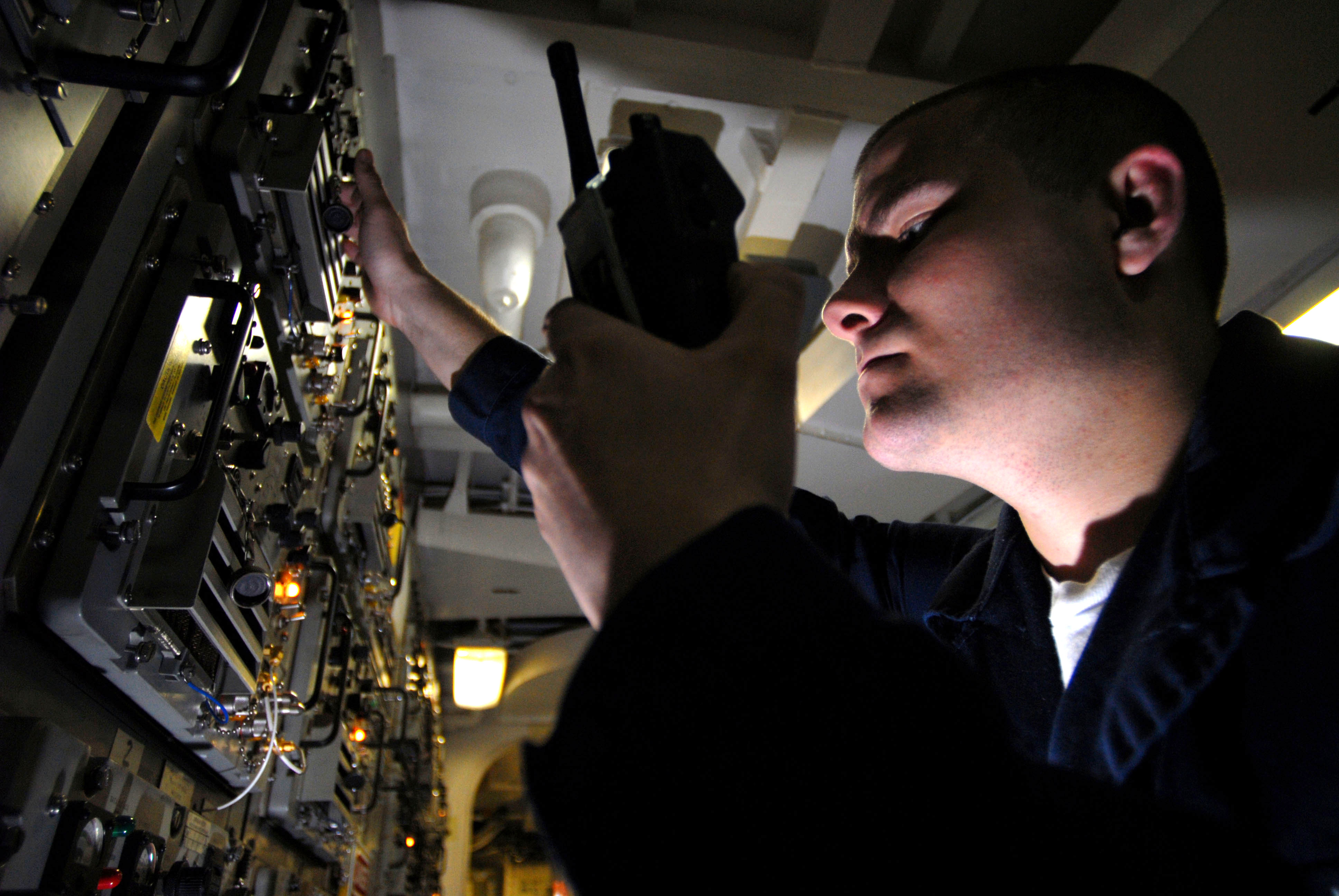
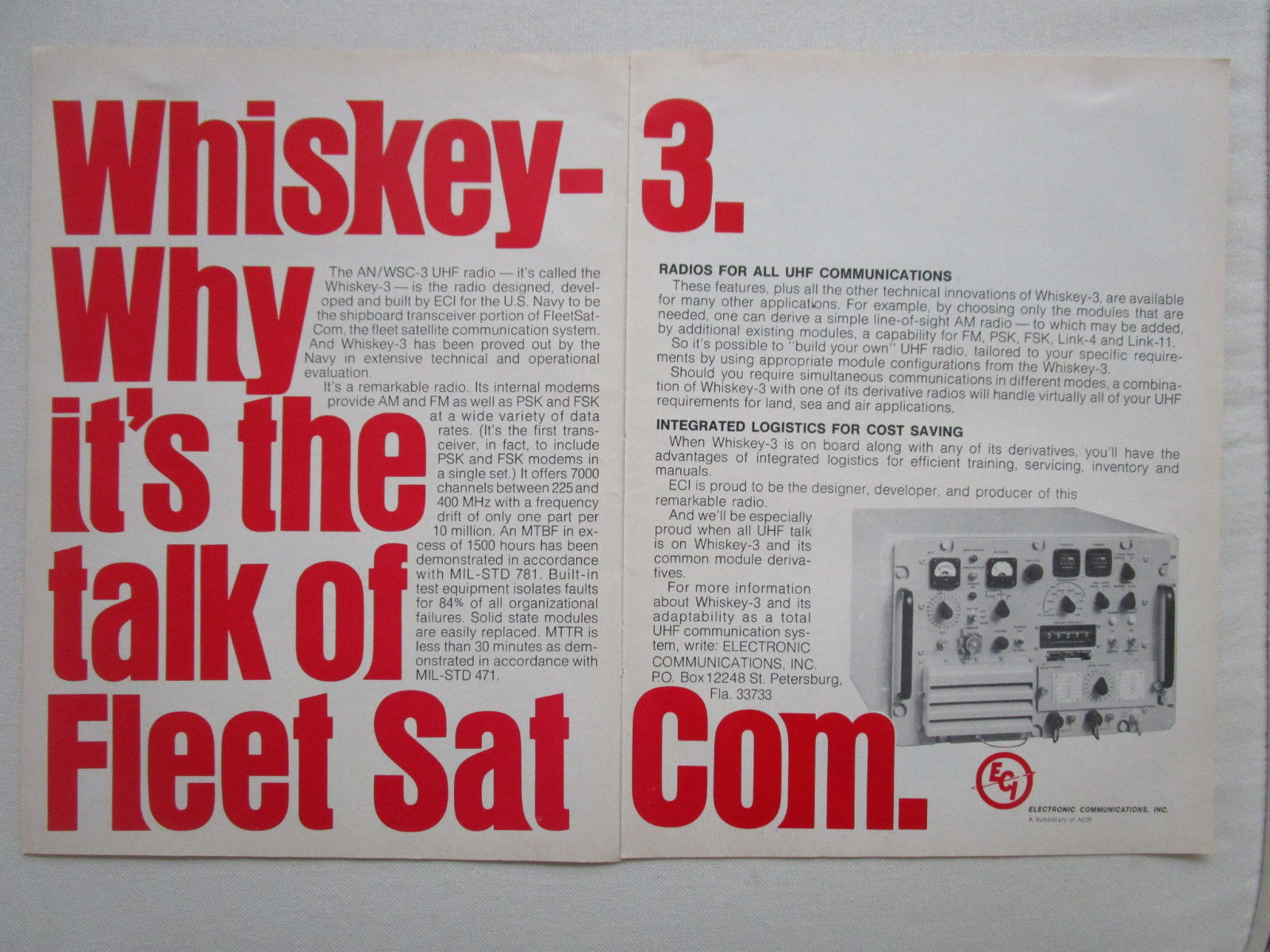
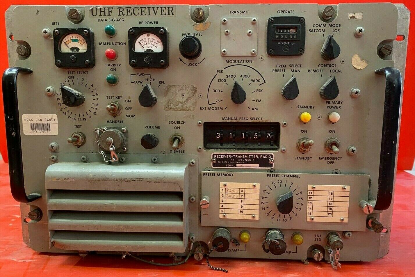
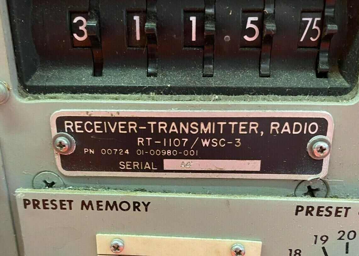
AN/WSC-3

AN/WSC-3 LOS/SATCOM 225-400mc transceiver
(aboard CVN-74)
AN/WSC-3 LOS/SATCOM 225-400mc transceiver
(aboard CVN-74)
WW2 era VHF and UHF transmitters
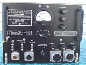
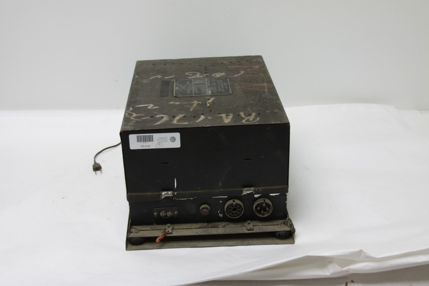
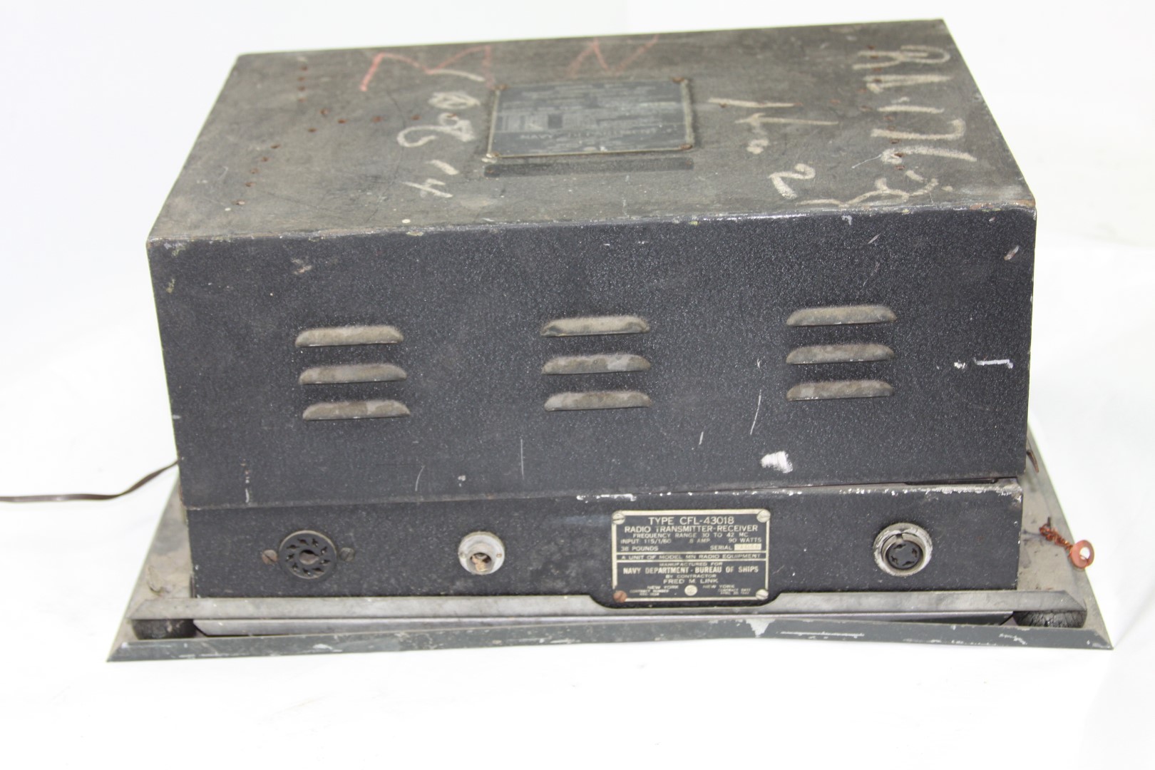
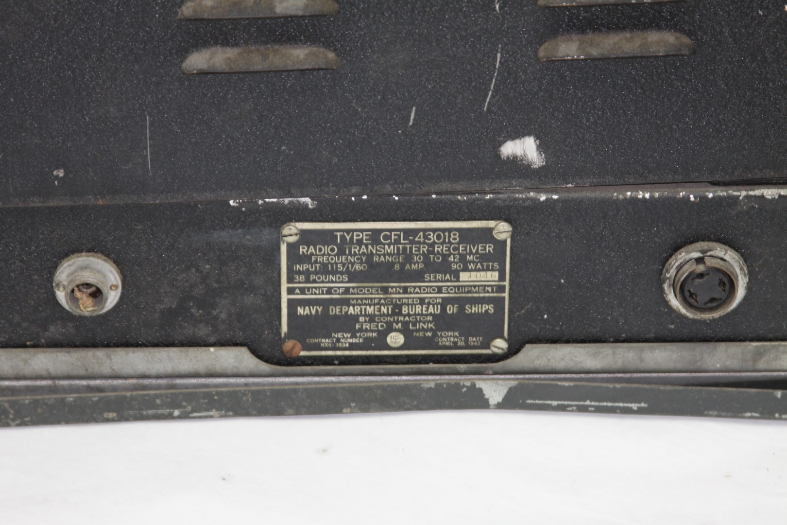
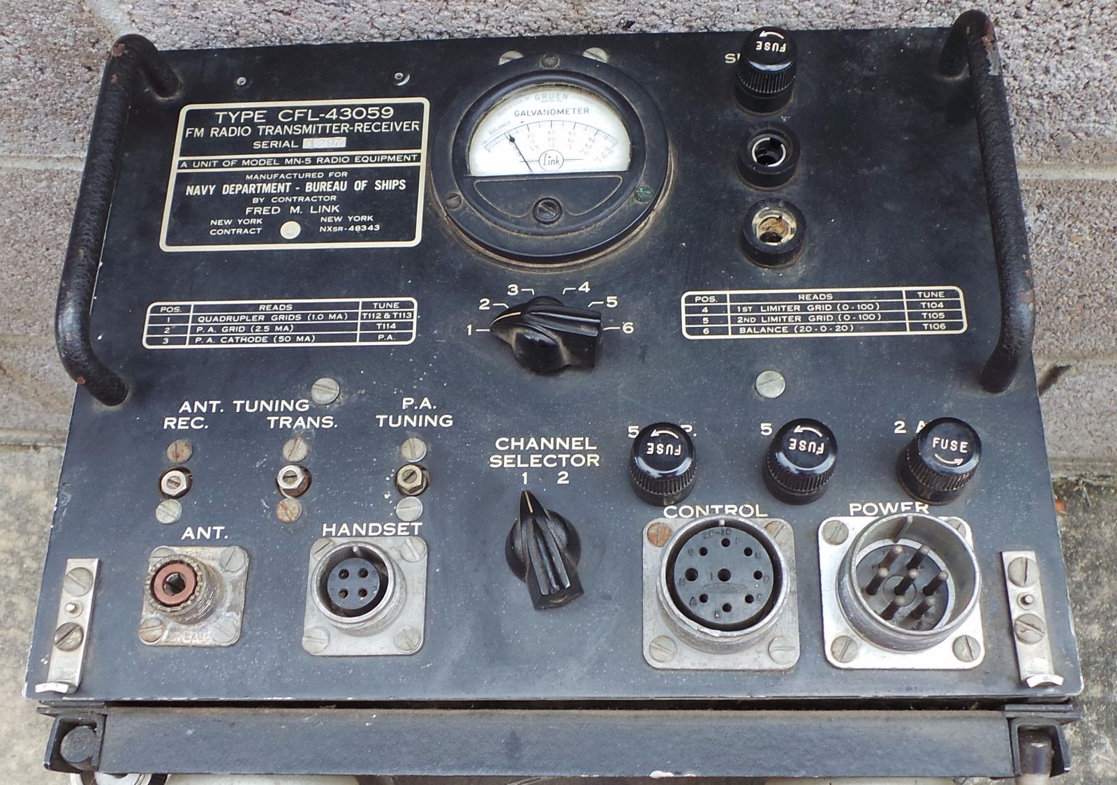
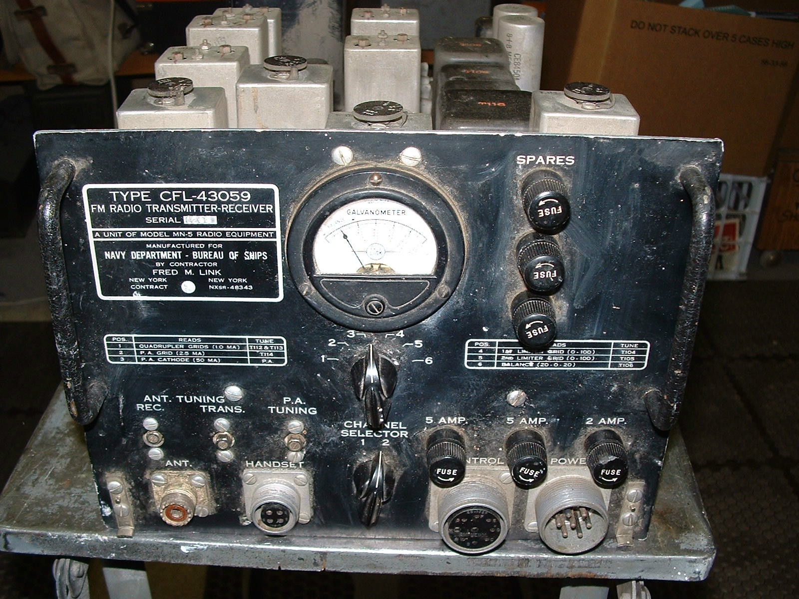
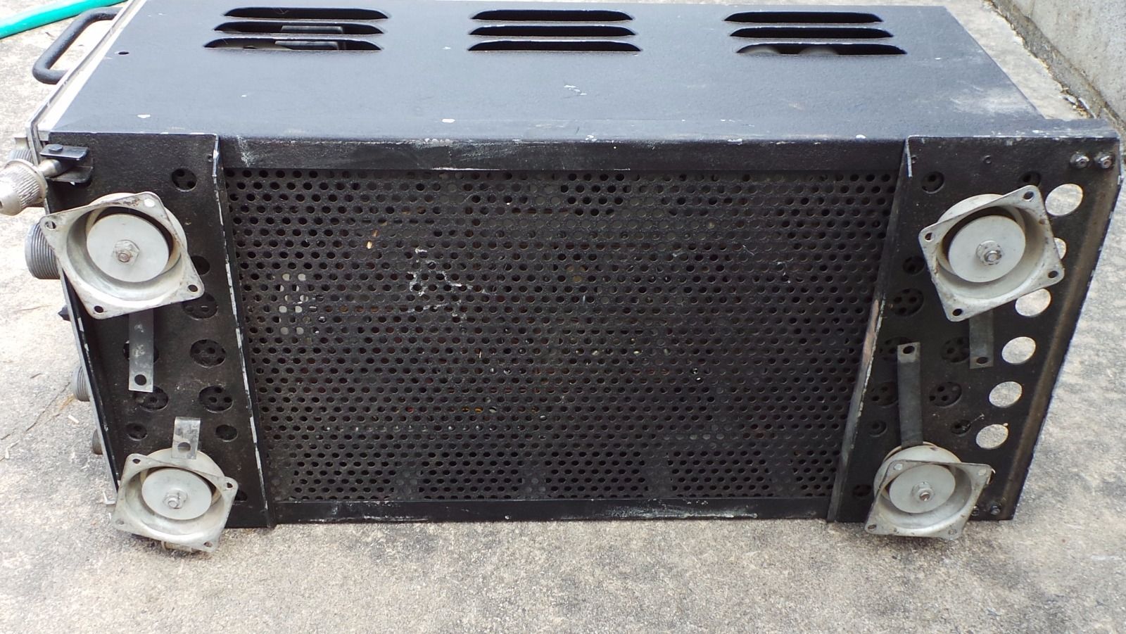
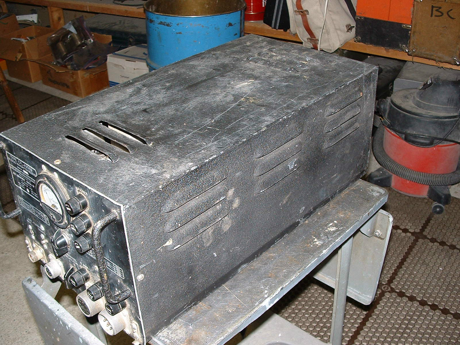
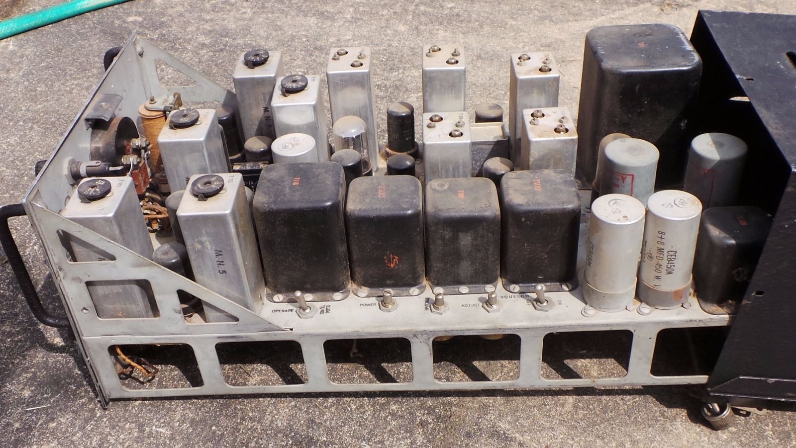
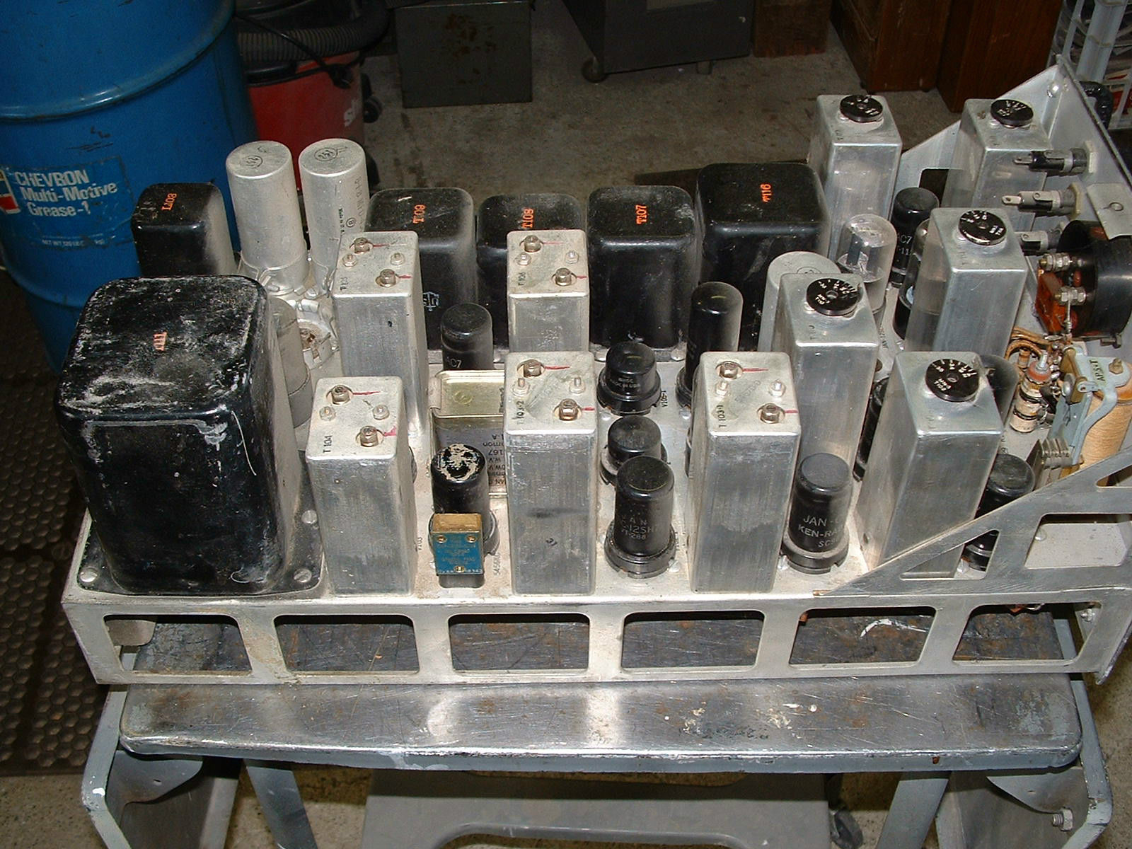
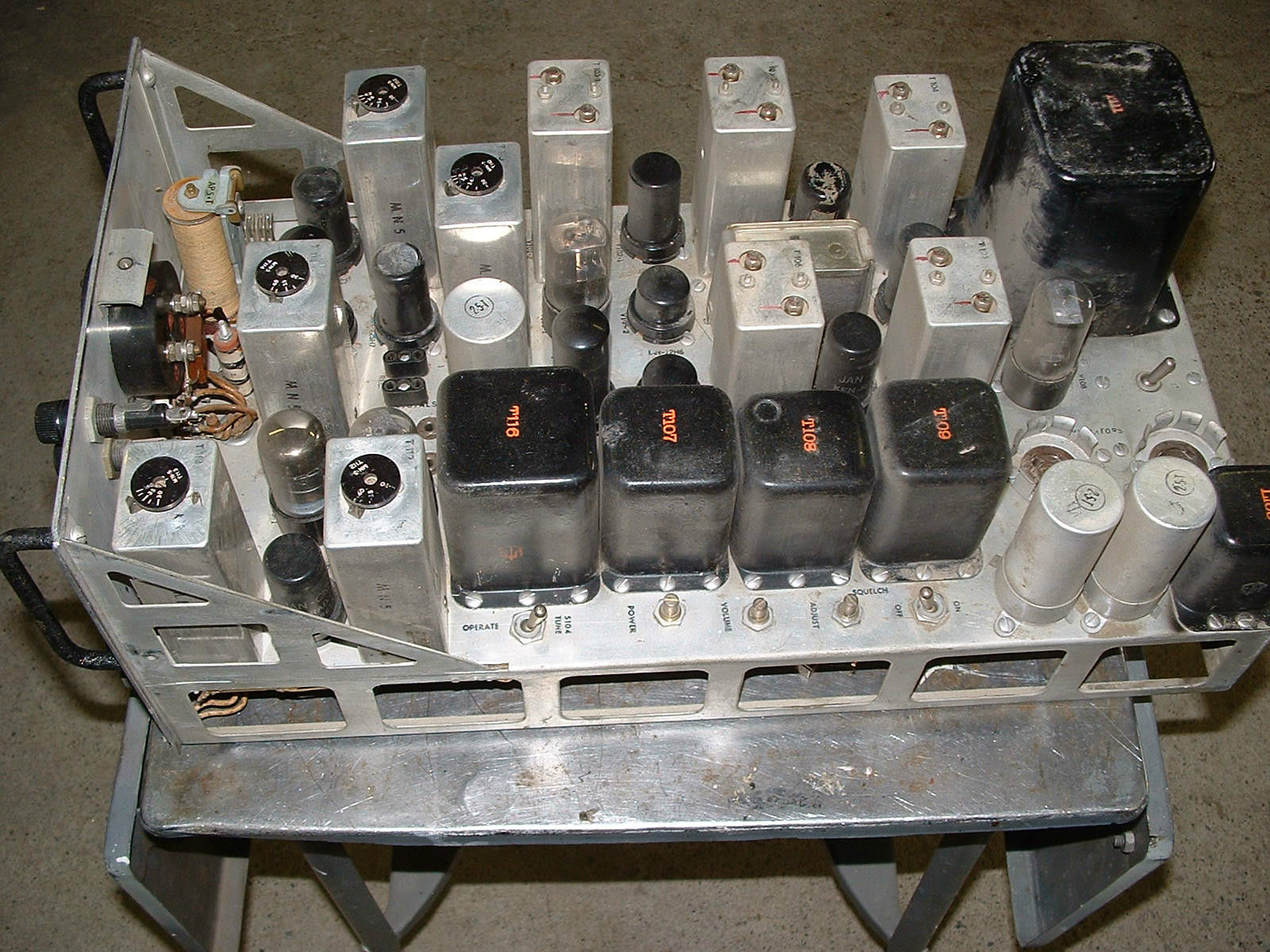
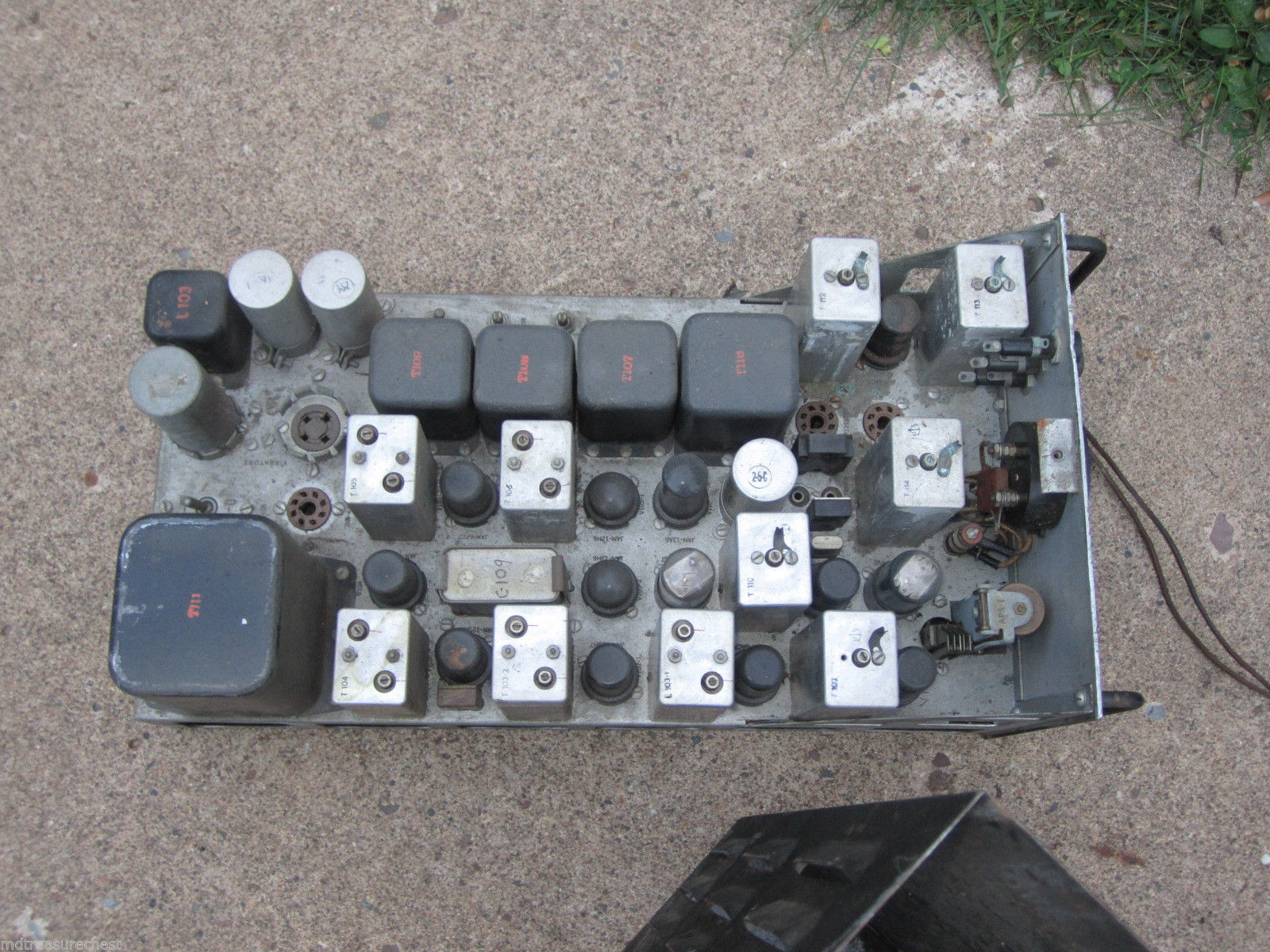
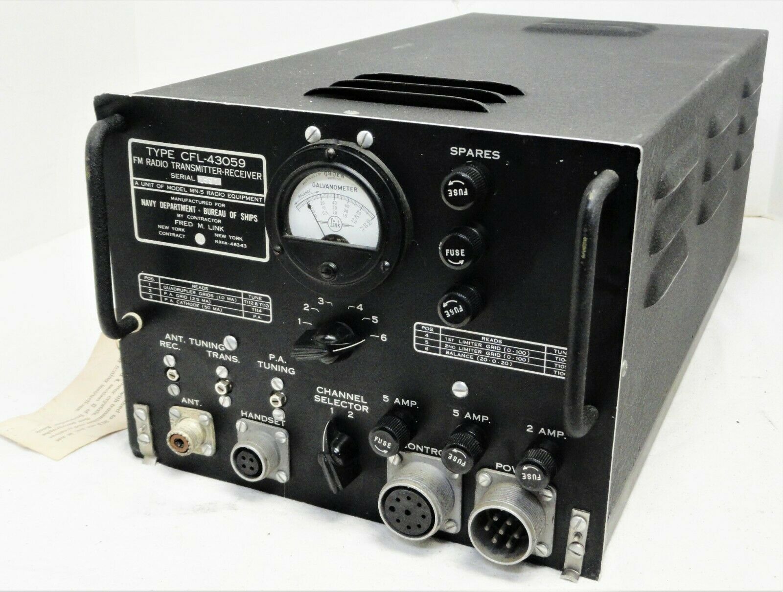
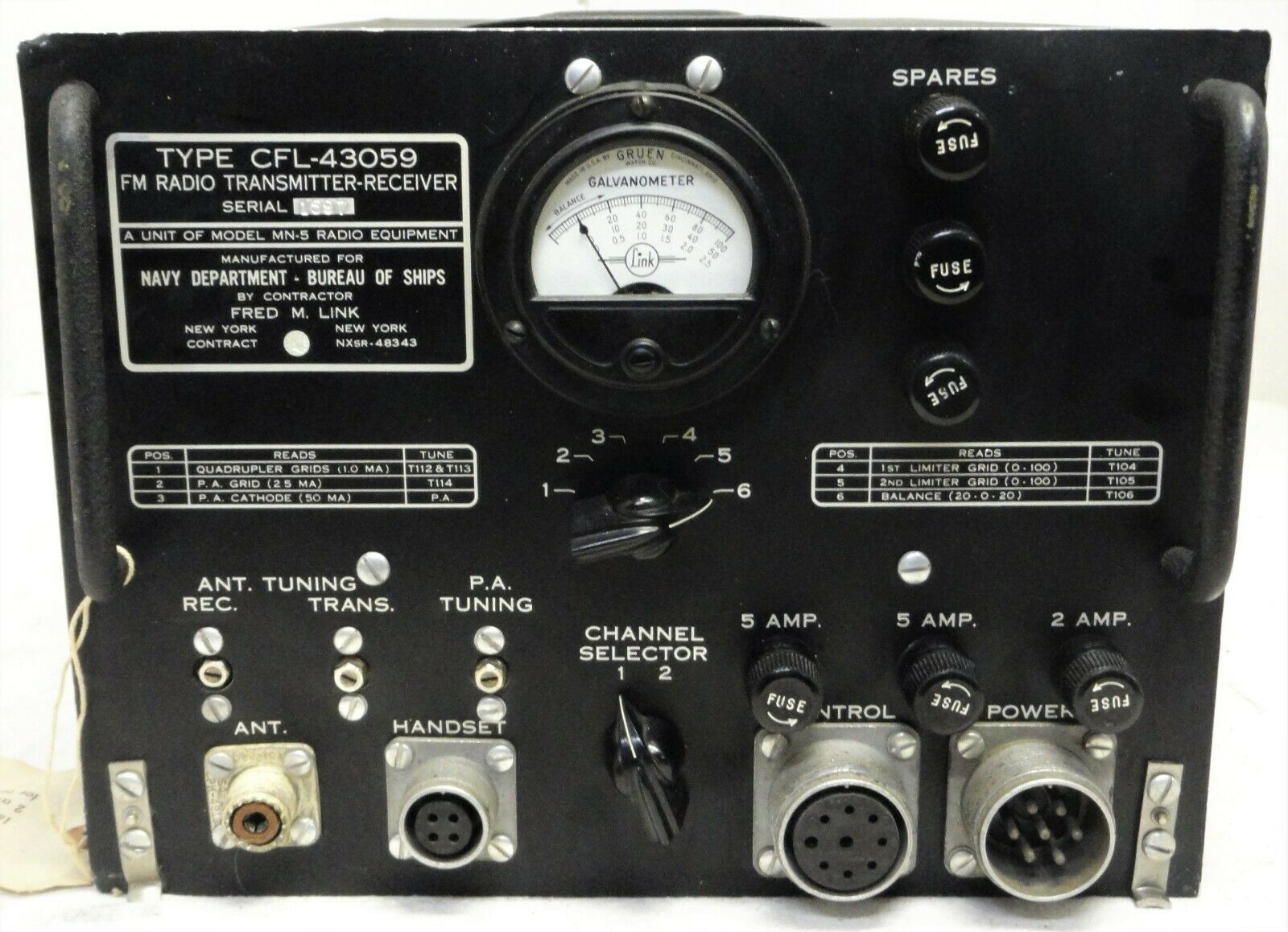
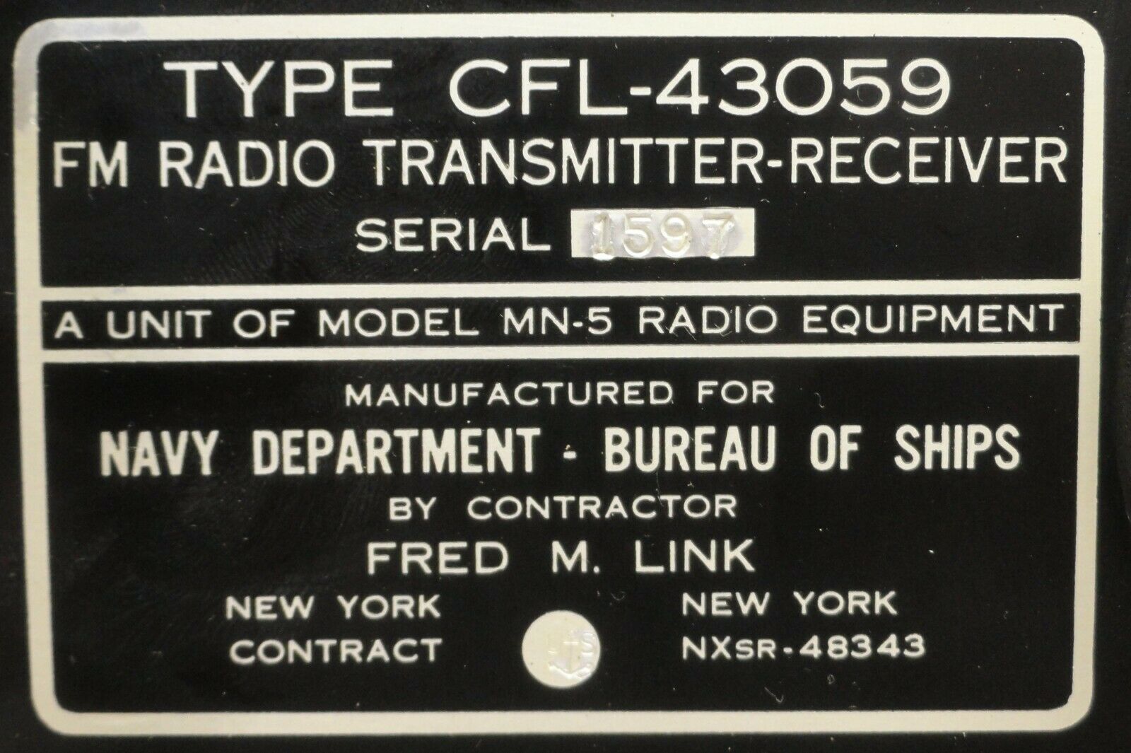
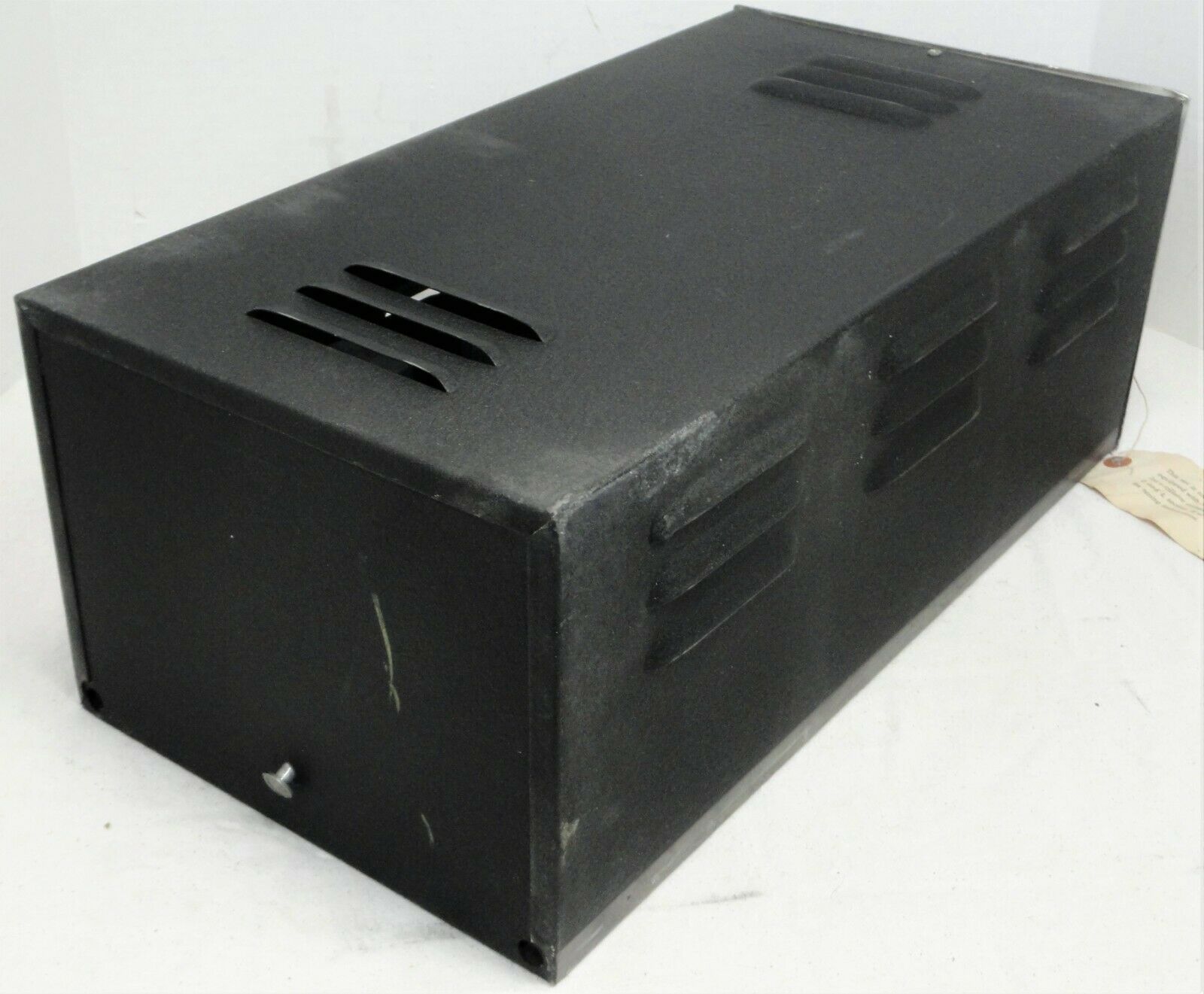
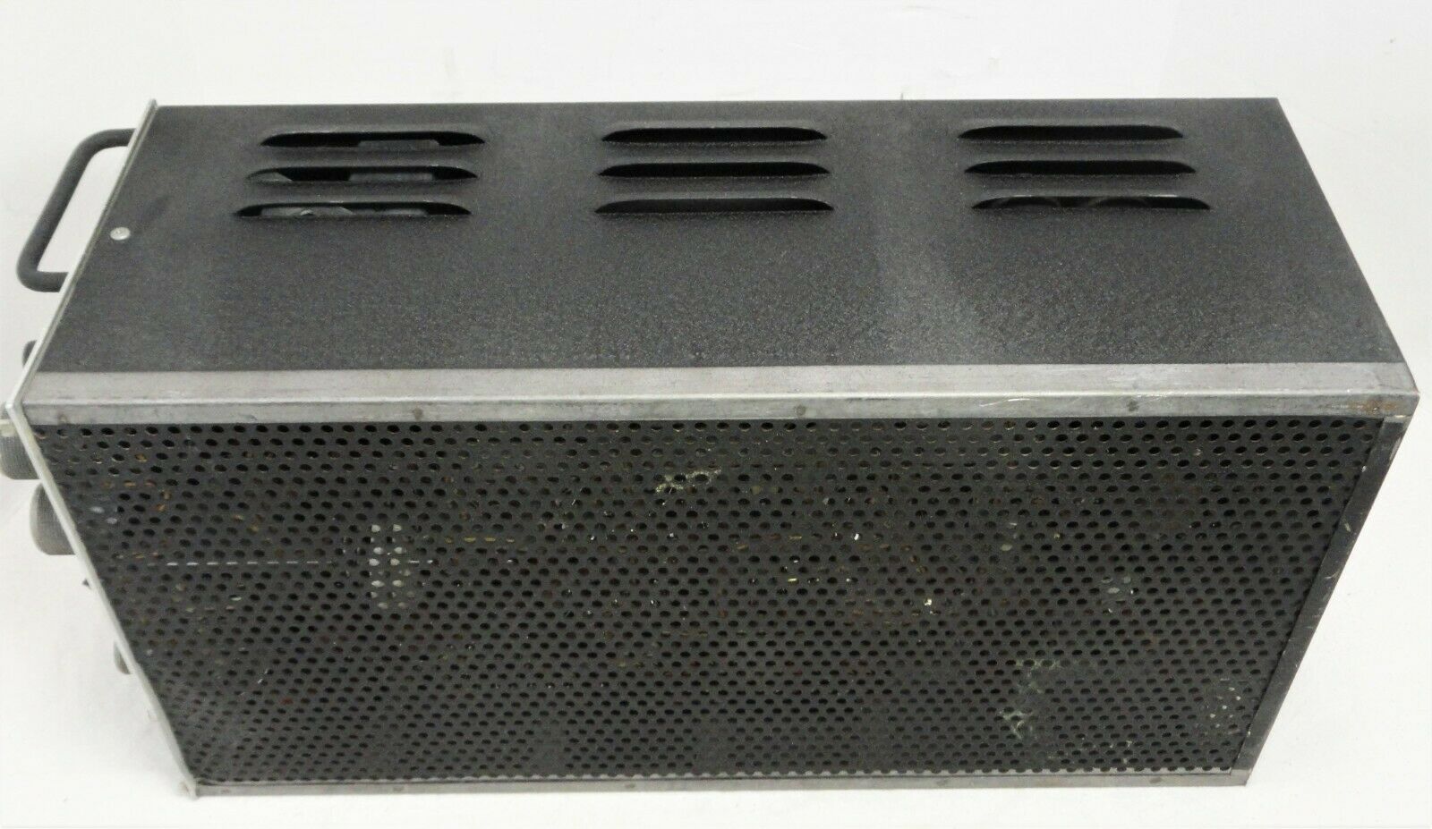
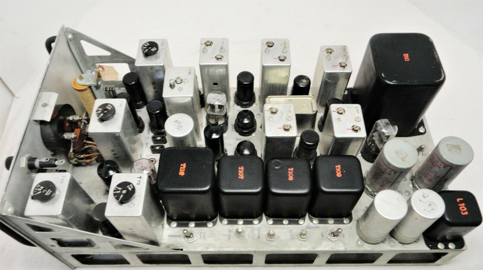
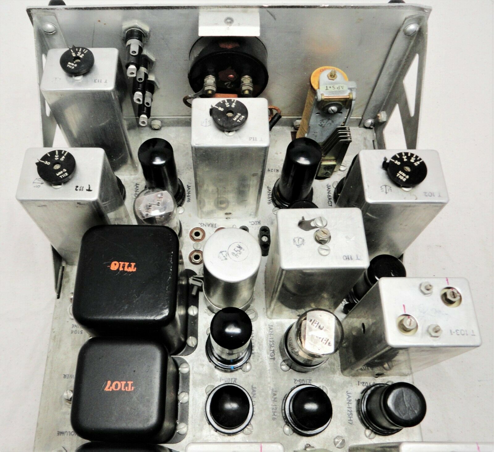
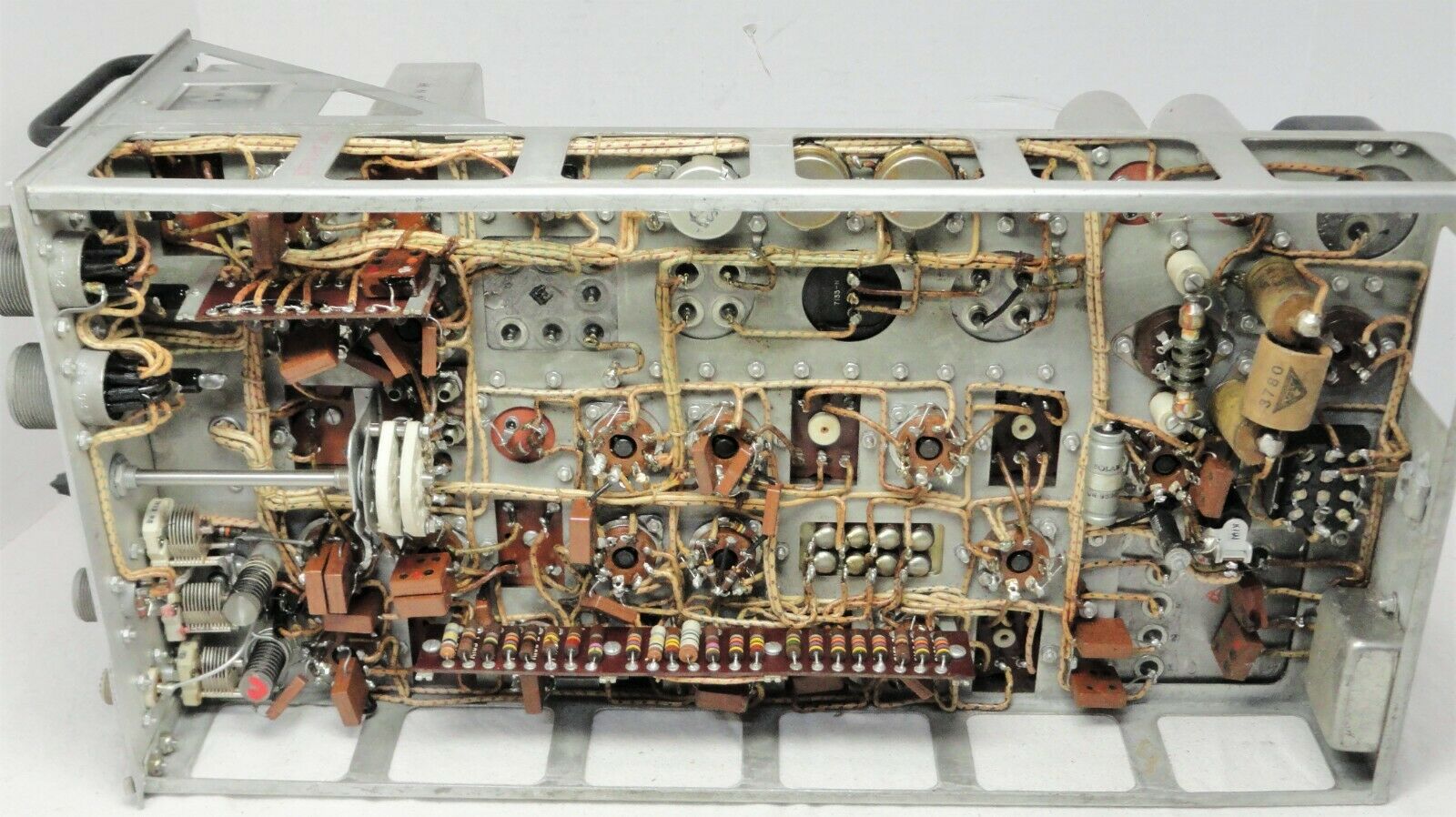
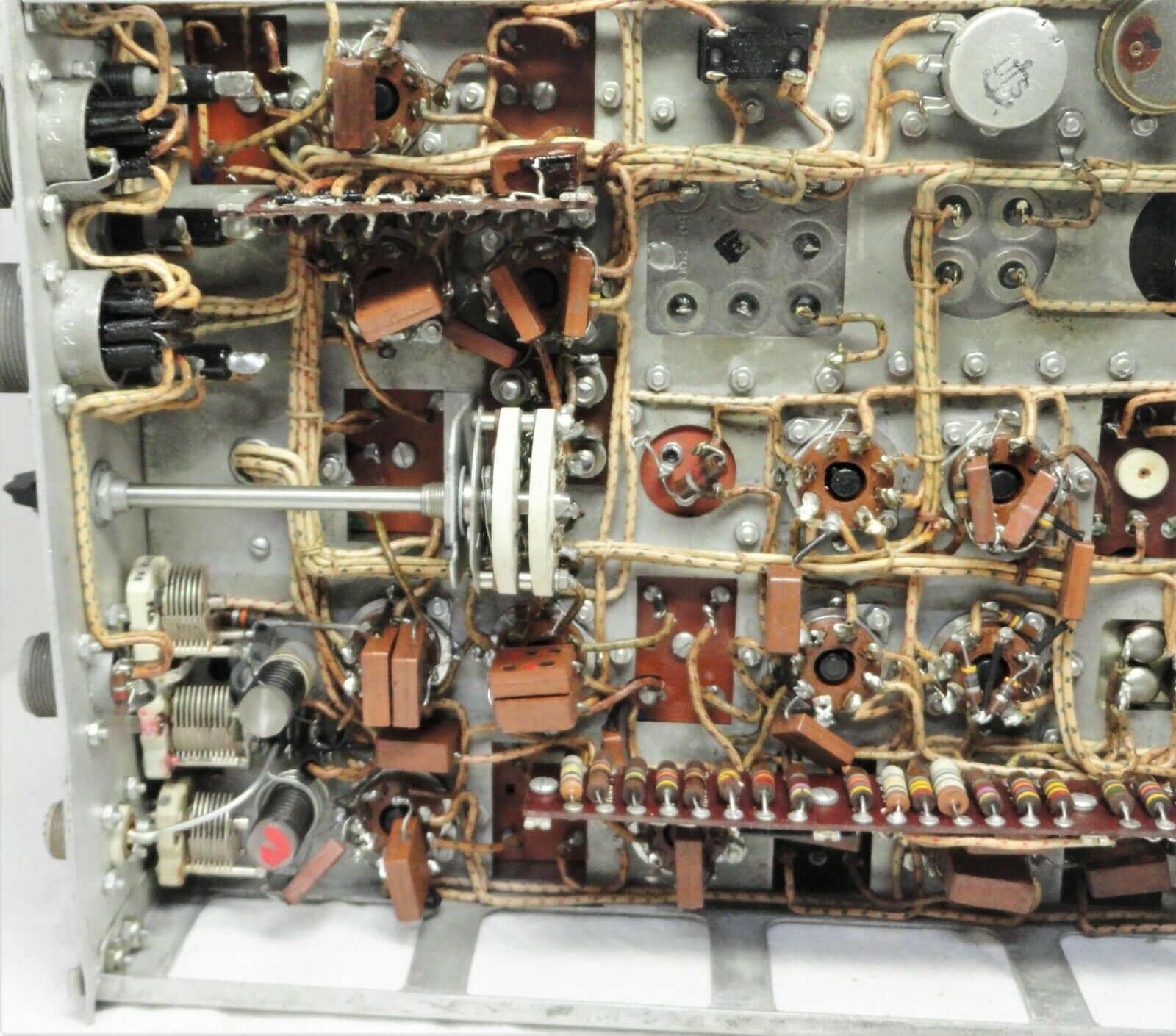
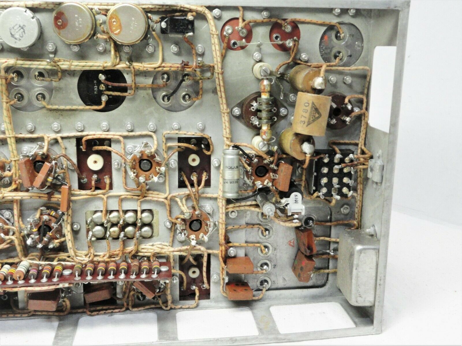
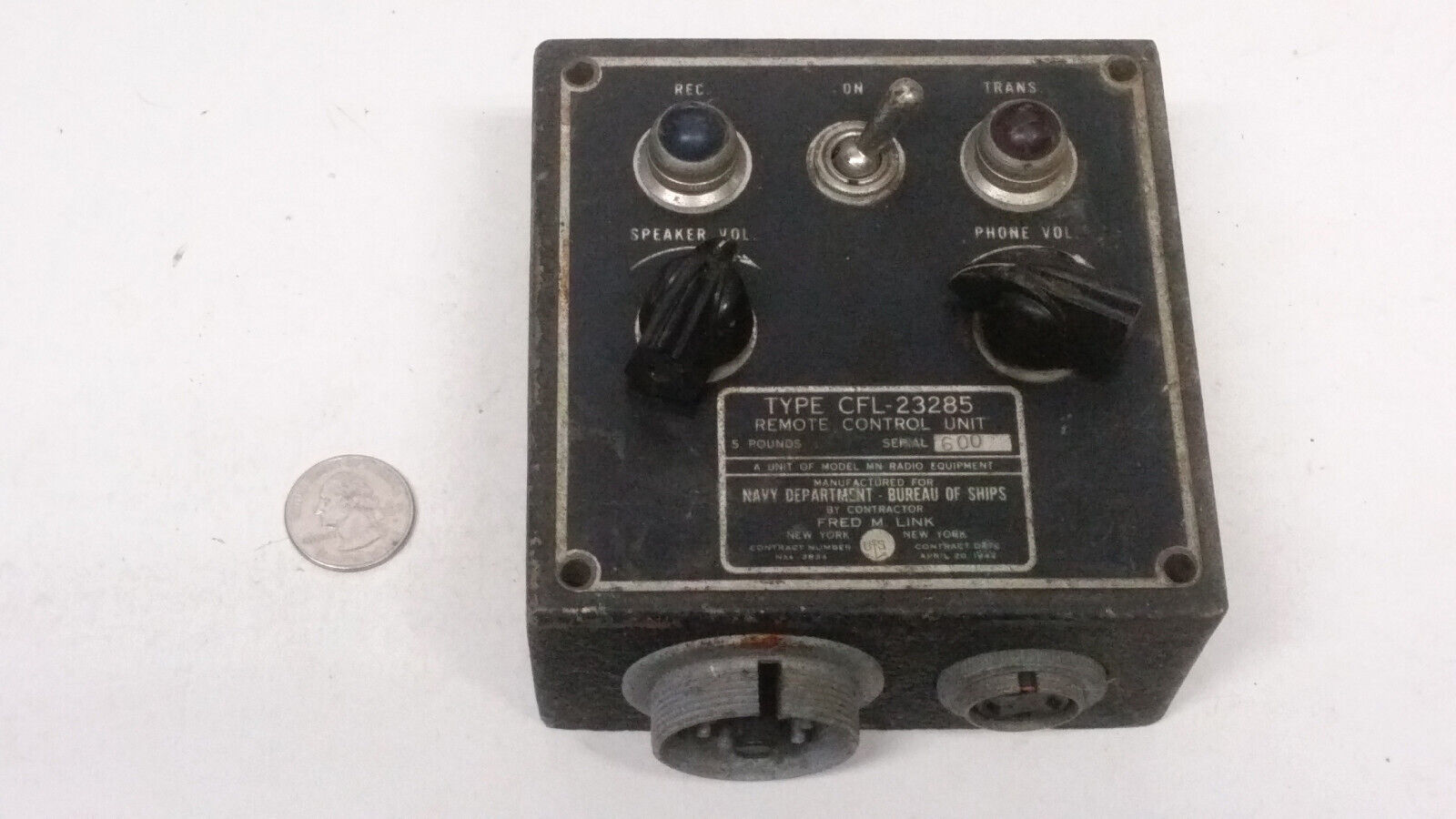
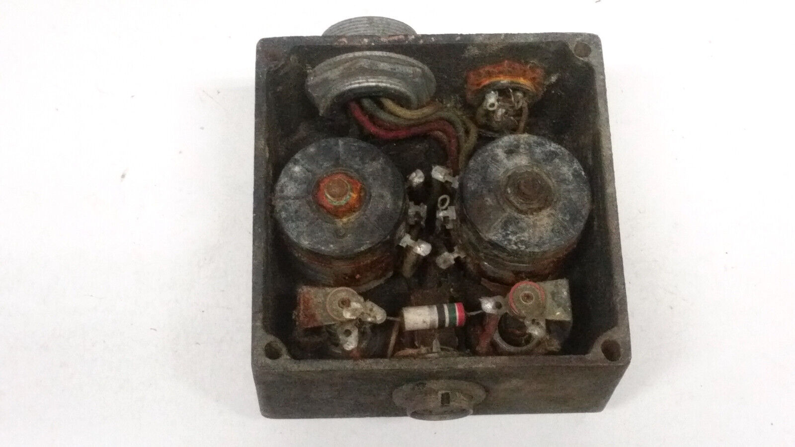
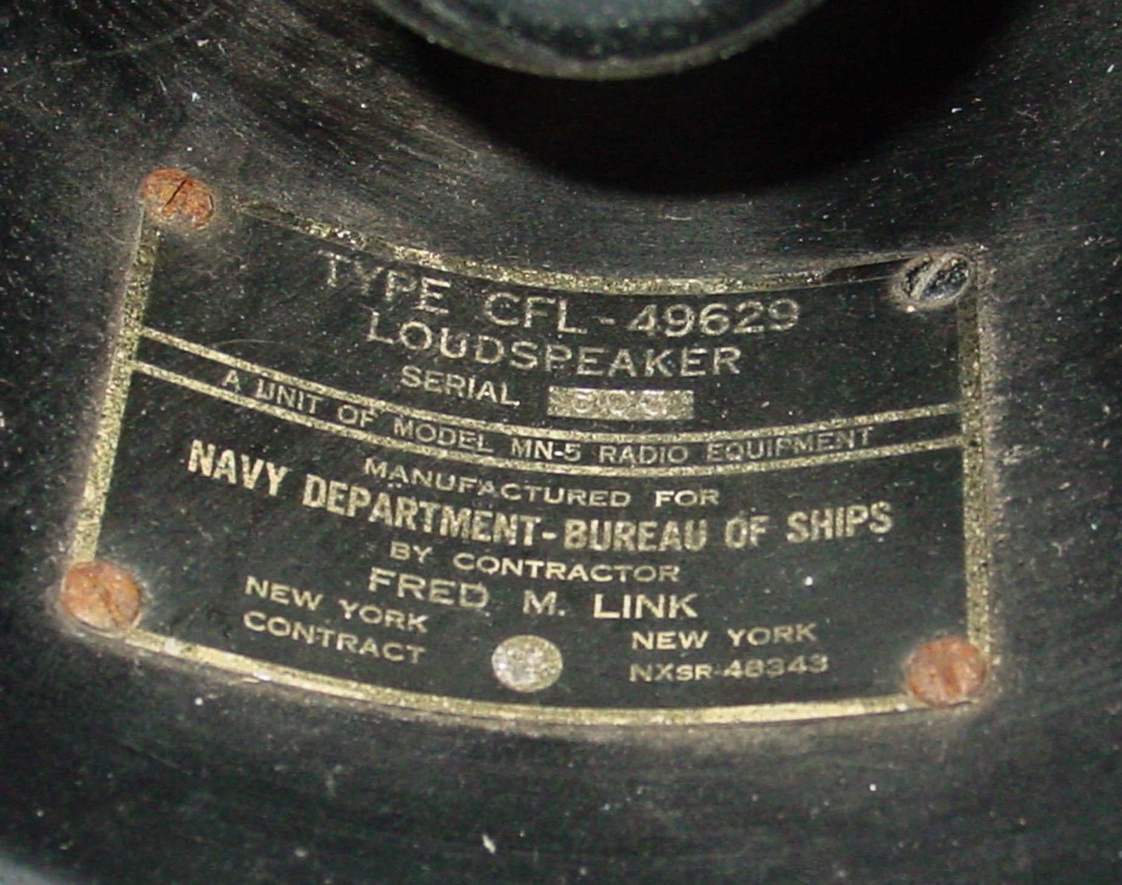
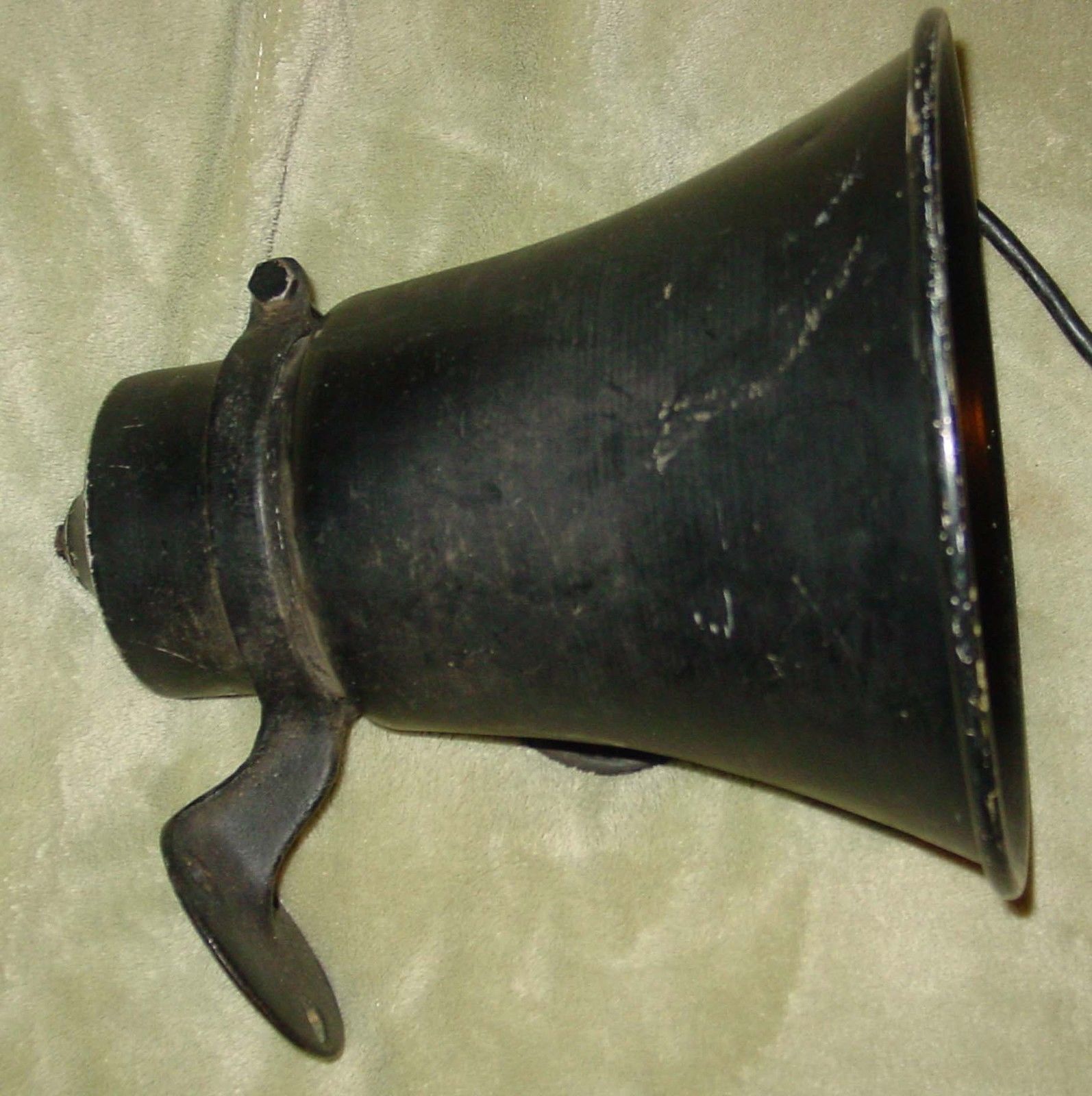
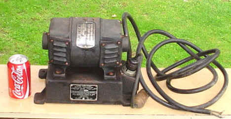
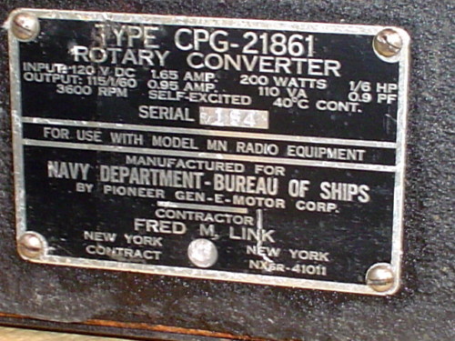
MN-5 transmitter-receiver
(CFL-43059)
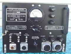
FM 30-42 mc - Manuf by Link
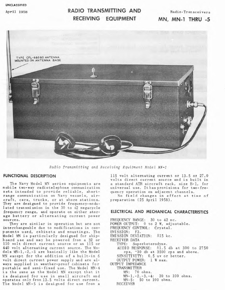
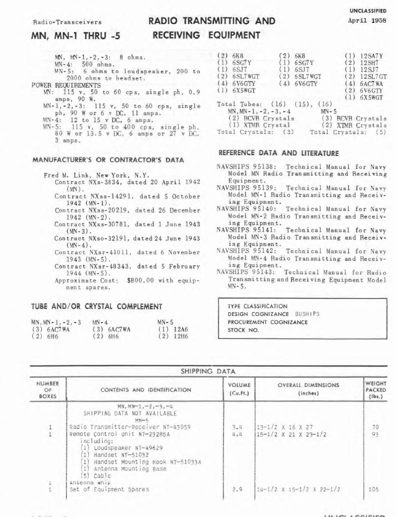
They are similar in operation but are not interchangeable due to modifications in components used, cabinets and mountings. The Model MN is particularly designed for shipboard use and may be powered from a 32 or 110 volt direct current source or an 115 or 440 volt alternating current source. The Models MN-1, -2, -3 are basically like the Model MN except f or the addition of a built-in 6 volt direct current power supply and are always supplied in weather-proof cabinets for portable and semi-fixed use. The Model MN-4 is the same as the Model MN except that it is designed for use in small aircraft and operates only from 13.5 volts direct current. The Model MN-5 is designed £or use from a 115 volt alternating current or 13.5 or 27.0 volts direct current source and is built in a standard ATR aircraft rack, size B-1, for universal use. It has provisions for two-frequency operation on adjacent channels.


TBS
More TBS Photos and Info
TBS ESO Catalog Entry
TBS Spec Sheets
TBS aboard USS Massachusetts

Manual - download 110 MB pdf

More TBS Photos and Info
TBT
50w phone, 60-200mc
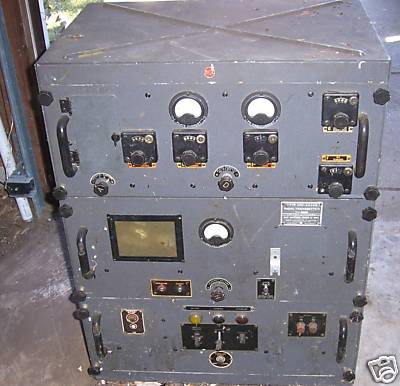
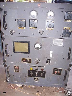
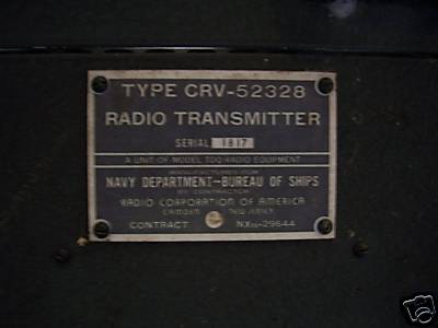
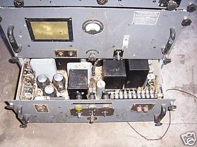
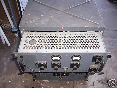
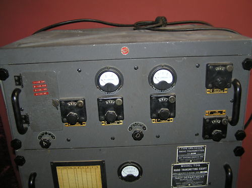
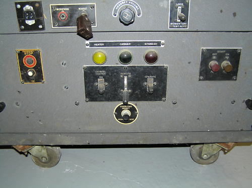
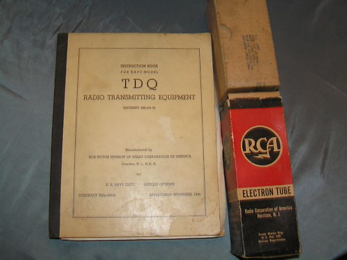
TDQ


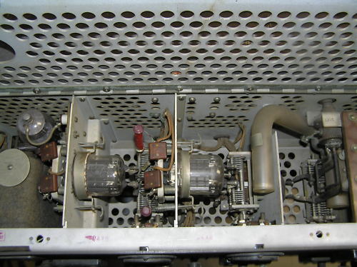

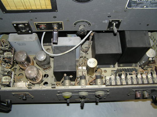
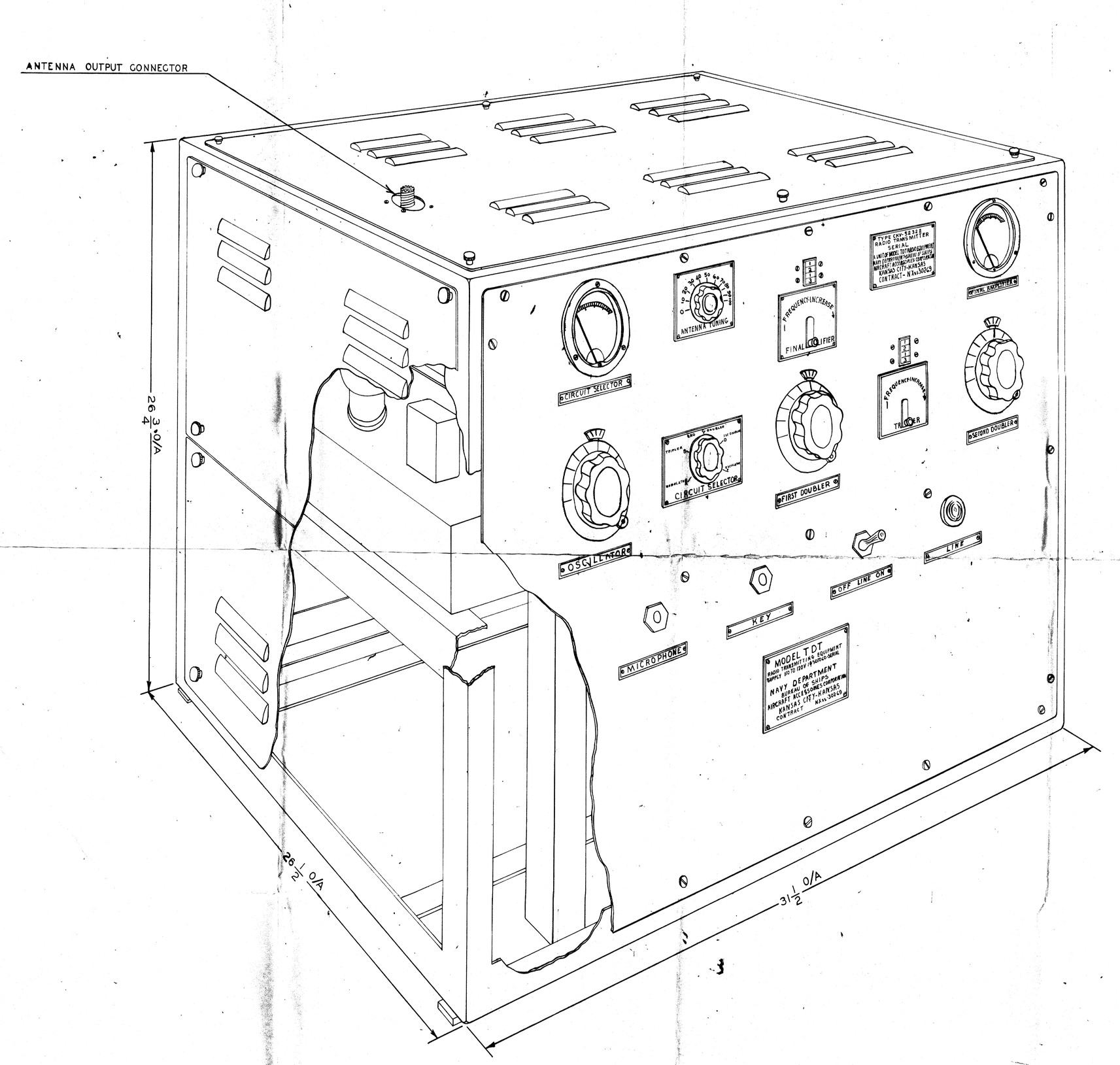
TDT VHF AM transmitter
VHF 115-156 mc AM
35w output


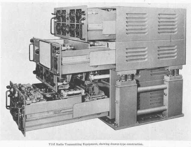
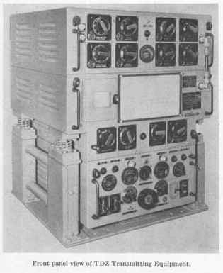
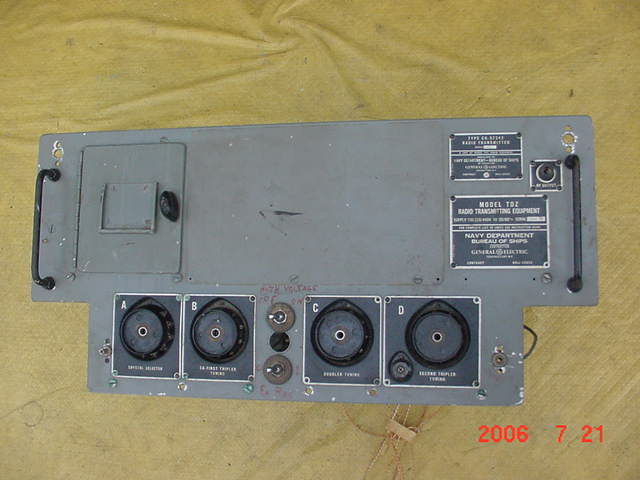
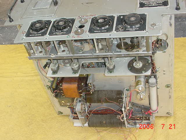
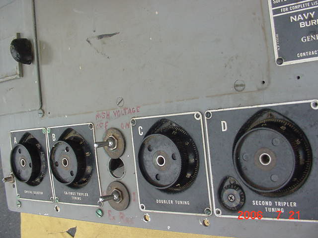
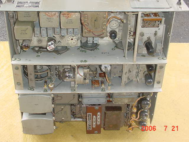
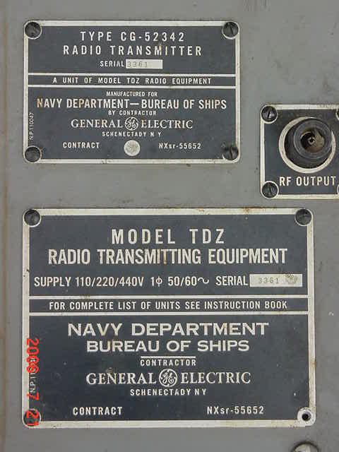
TDZ
225-400 Mc AM
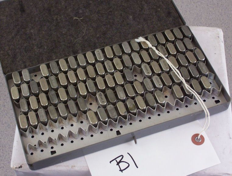
10 crystal controlled channels
--

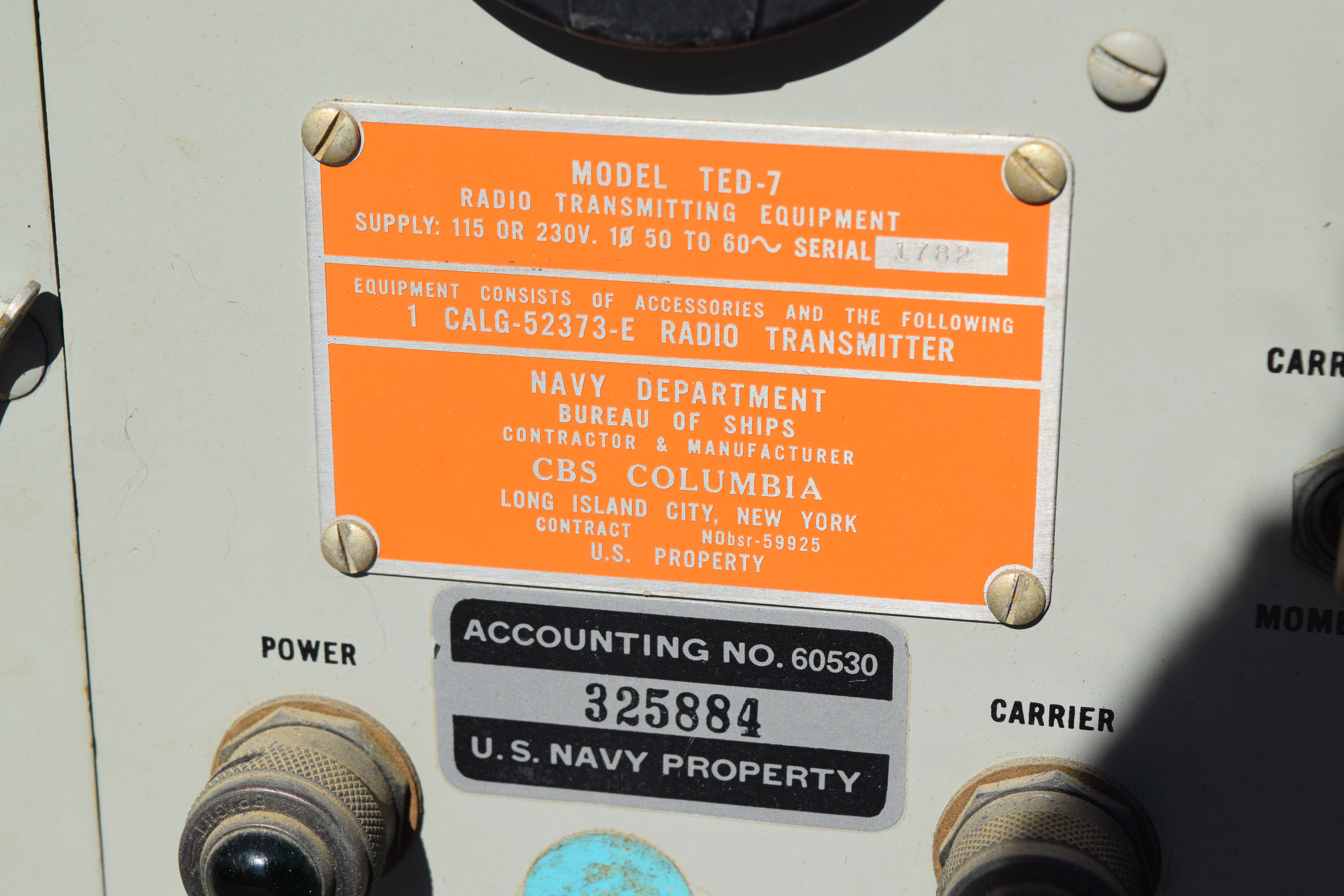
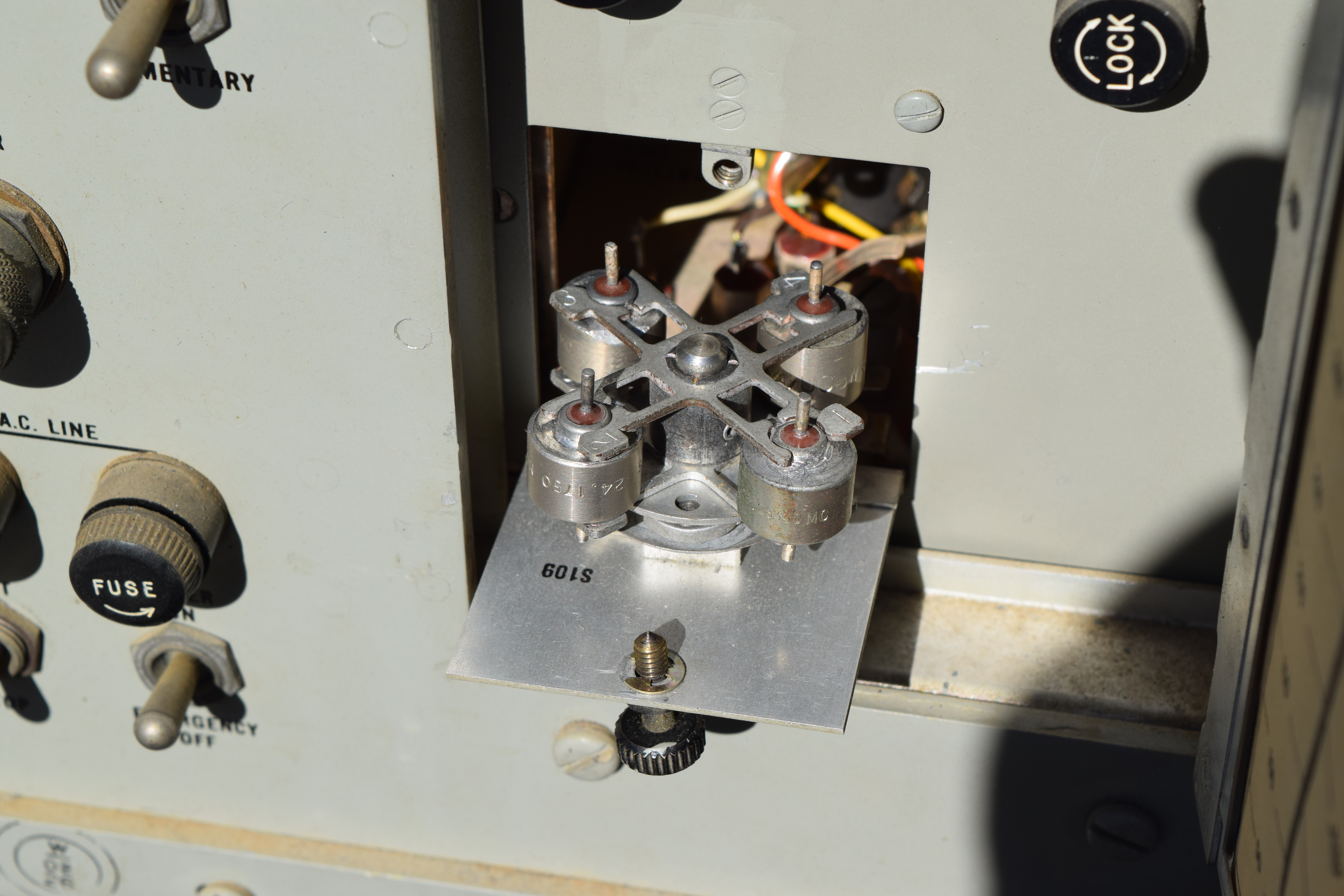
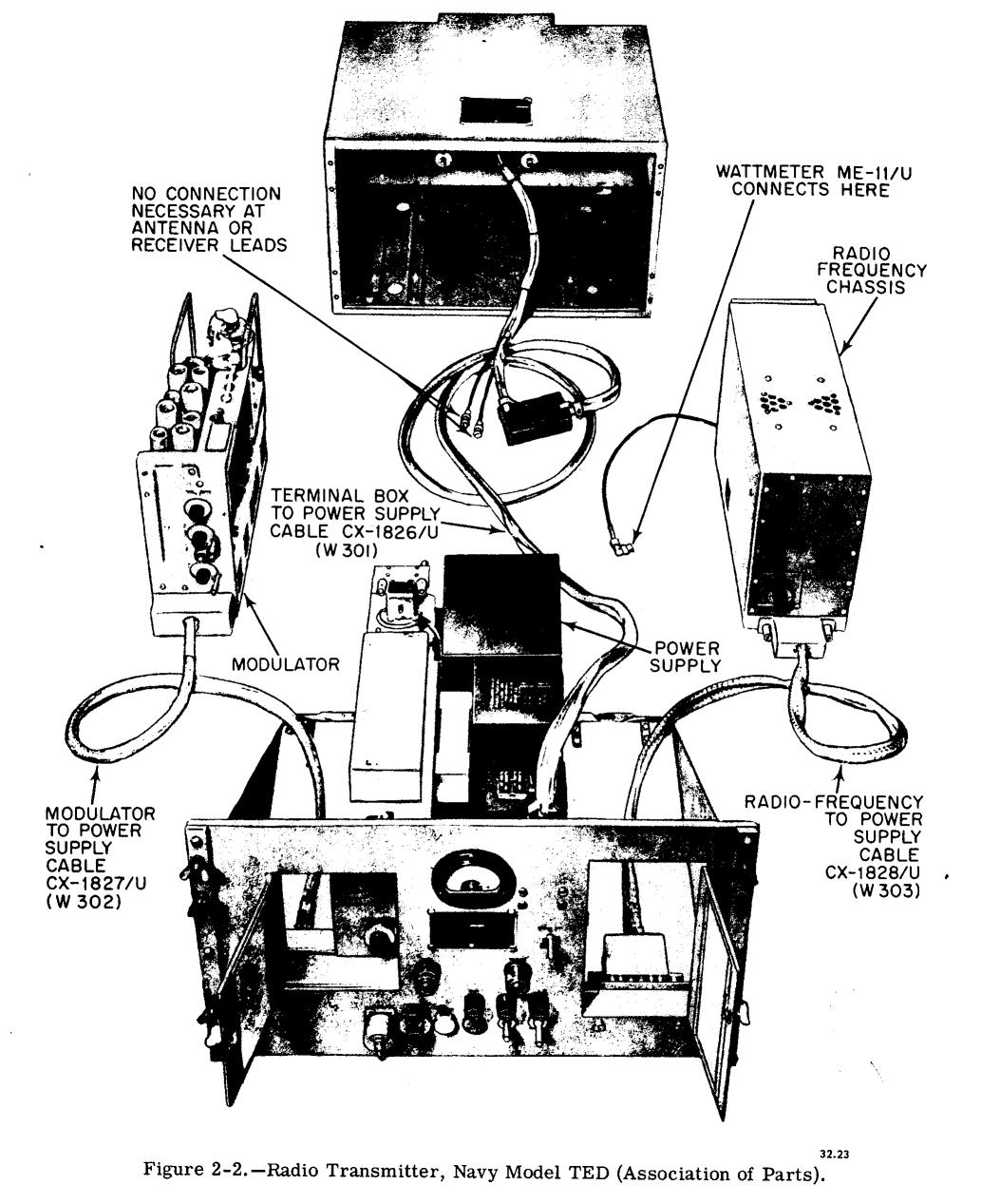
TED UHF Transmitter
TED-6
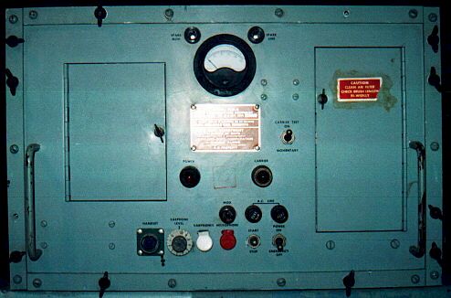
15 watts output
Circuit Description - 4.5 MB pdf