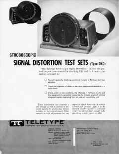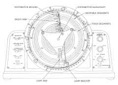

- To transmit signals for testing Teletype start-stop printing telegraph circuits, and checking the efficiency of Teletype startstop selectors. These signals are a repetition of any of the following test signals: TEST MESSAGE, R, Y, T, O, M, V, LETTERS, or BLANK or CODE LENGTH MARKING IMPULSE, either undistorted or with controlled degree of distortion up to approximately 100 per cent.
- To measure accurately, through use of the applicable test set, the impulse lengths of five level code signals originating from an external transmitting unit. Synchronous motors with identical gear reductions on each unit operating on the same source of power are necessary for accuracy because the transmitting unit and the test set must be kept in exact phase relation. If one of the units is equipped with a governed motor, a slight speed variation will cause a wavering of the impulse lengths as viewed on the stroboscope, making them difficult to measure accurately.
- To check the operation of relays or start-stop regenerative repeaters in a local circuit. When using the test set in this manner, transmitted signals from the test set operate the relay or regenerative repeater being tested, and these signals in turn are routed to the test set stroboscope for observation.
Distortion produced in the transmitted signals may be any of the following types:
- MARKING BIAS, which advances the beginning of each marking impulse with respect to the beginning of the character cycle.
- SPACING BIAS, which delays the beginning of each marking impulse.
- (3) MARKING END DISTORTION, which delays the end of each marking impulse.
- (4) SPACING END DISTORTION, which advances the end of each marking impulse.