US Navy Teletype Equipment and Emanations Security
Red/Black, RFI, TEMPEST, CRITICOM
Motivation - Early in the development of military teletype communications,
engineers discovered that the make/break of 60ma current loops created small
signals that could be propagated via electromagnetic radiation, or conducted
along signal and power lines. This meant that crypto systems could be vulnerable
if they also inadvertently emitted the plain text along with the desired
encrypted text. This discovery led to efforts to reduce the undesired signals
through shielding, filtering, and signal strength reduction. This program became
known as TEMPEST. Emanations Security is another name for this effort.
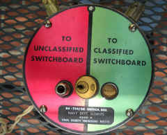
Red & Black - It is critical that plain text and encrypted text
should never be associated with each other. RED refers to signals that represent
classified plain text (which need to be hidden from public view). BLACK refers
to unclassified plain text or encrypted text (which may be intercepted during
transmission). RED and BLACK signals, equipment, and operating areas are kept as
separate as possible to minimize the possibility of RED signals appearing in
BLACK transmissions. Extensive guidelines for signal routing, grounding, etc.
should be followed.
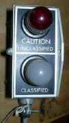
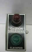
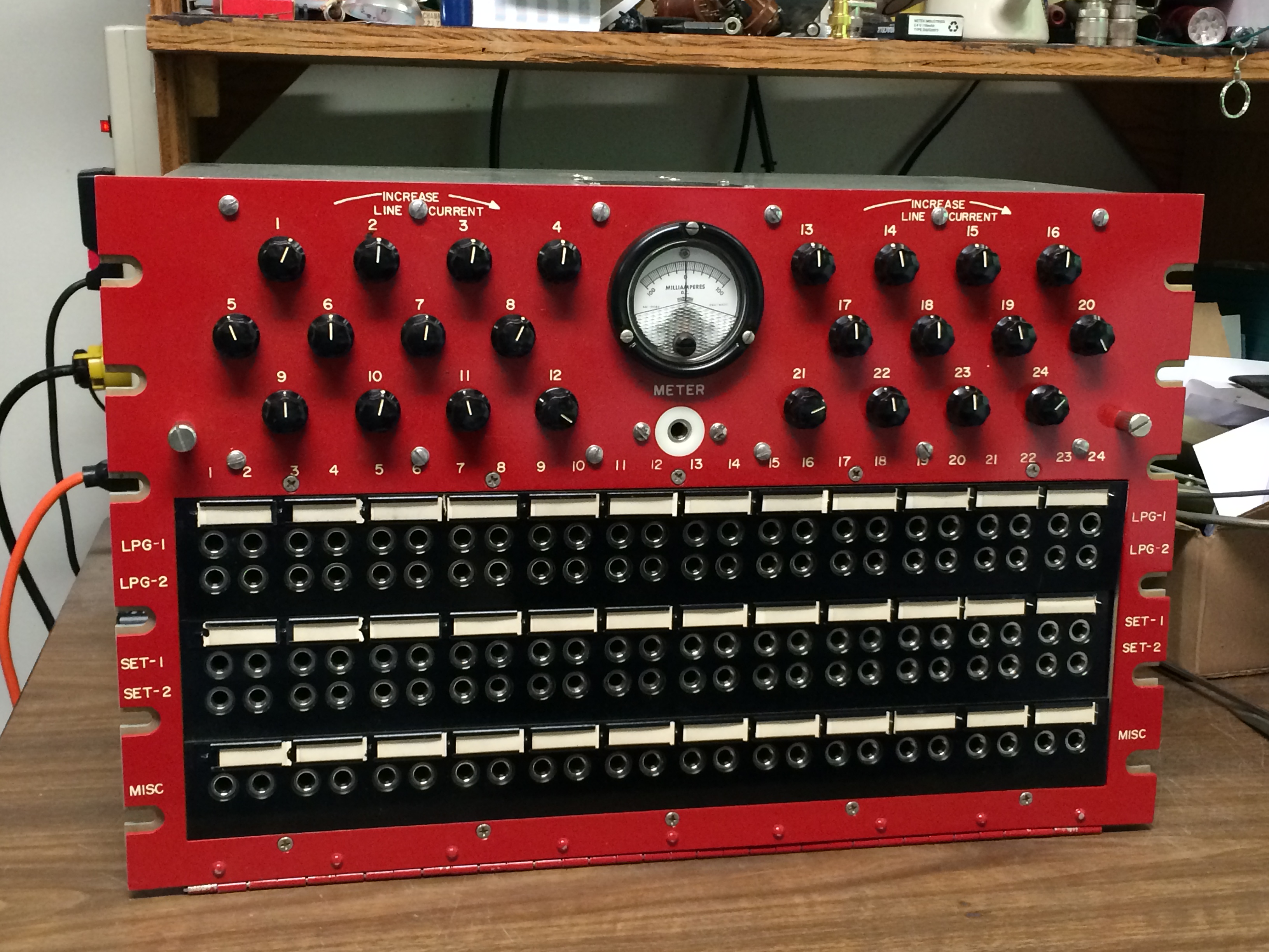
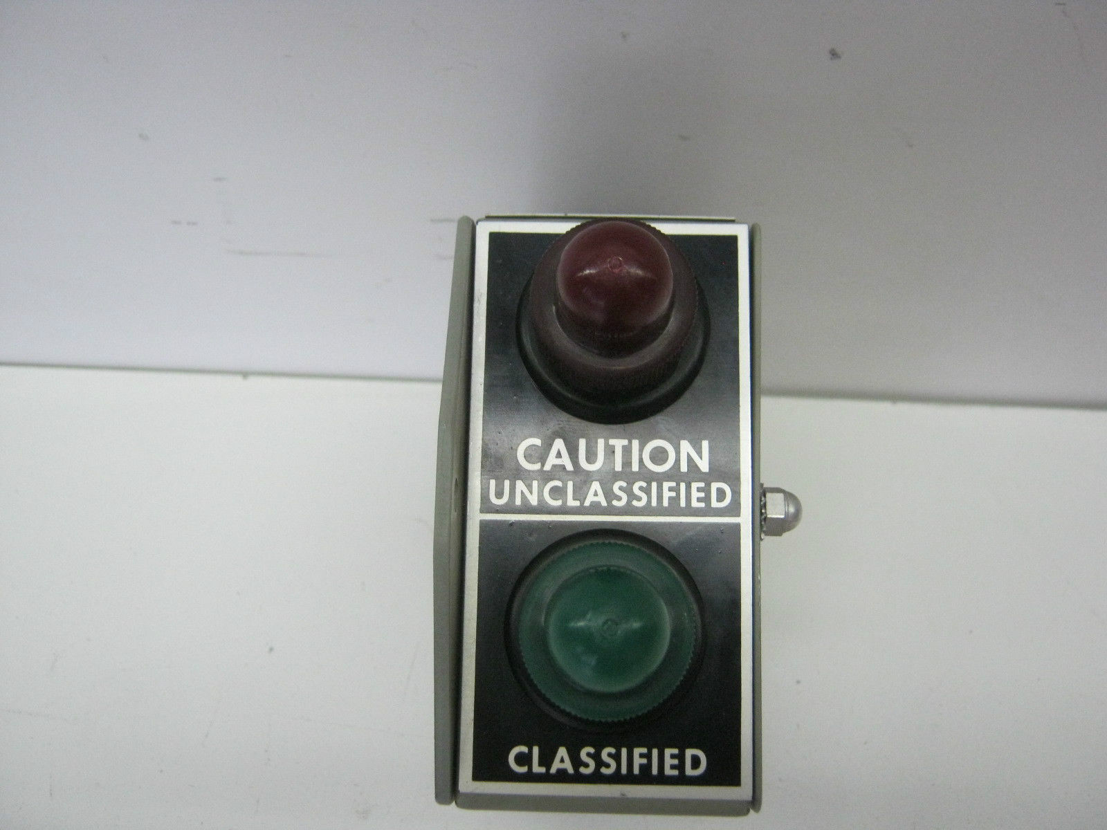
RED teletype signal patch panels are used on the plain text side of
encryption equipment and BLACK/GRAY patch panels on the encrypted side. If a piece of
teletype equipment can switched between the two, a locking switch and indicator
lamp are used to minimize mistakes.
SB-4035/UGQ Patch Panel
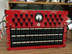 |
SB-4034/UG Patch Panel
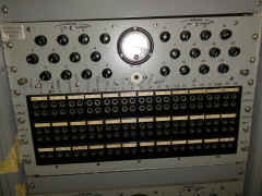 |
SA-734/SG Switch
|
ID-866/SG Indicator
|
Low Level Signaling - To reduce unwanted emissions, the military
adopted +/- 6vdc signaling (MIL-STD-188B) to replace the earlier 60ma current
loop (High Level) signaling. This low level signaling greatly reduced emanations
security problems. Existing High Level equipment could be converted to Low Level
by the addition of Electrical Service Units which converted the signals. New Low
Level equivalents for most older models were also produced - these had more
extensive shielding and filtering as well as the Electrical Service Units. See The 1977 Index for a
full listing of high-level and low-level equipments. See NAVSHIPS
0967-173-7030
and 0967-173-7040 for maintenance details on low-level equipments.
Also see
0967-391-6010 "Low Level Technical Control Equipment". Also
see more info below.
Teletype Corp. Equipment - The terms RFI, TEMPEST, and CRITICOM
show up in Teletype publications. Here are my guesses as to meaning -
RFI Suppression - In early publications, RFI (Radio Frequency
Interference) suppression meant the addition of spark suppression filters to
signal and power lines in order to minimize interference to radio receivers. Later publications, like 311B/RF,
use RFI to mean +/- 6vdc Low Level signaling in addition to shielding and
filtering (TEMPEST). 311B/RF says "RFI suppression as applied to
teletypewriter equipment is accomplished by means of shielding and wave shaping
a low level electrical telegraph signal throughout the equipment. The
installations vary with each set, but produce the same results of insuring
signal line privacy."
TEMPEST - shielding and +/- 6vdc Low Level signaling. A typical
Teletype Corp. spec would say "Includes MIL-STD-188B six volt polar
interface and Teletype's TEMPEST feature."
CRITICOM - CRITICOM or CRITICOMM refers to very
high priority intelligence communications (see also original NSA
document) Both High-Level and Low-Level sets are listed as "CRITICOMM type". The
270B manual for CRITICOM sets does not mention the word "CRITICOM",
but the sets are 7.00 unit, polar signal, with stunt box contacts for
recognizing message Z signals related to CRITIC messages (ZYH, ZEM, ZYI, ZYE,
"X CRITIC", and message start/end ZCZC and NNNN). CRITICOM equipments
appear to be unrelated to Emanations Security.
NIK - Normal Input Keying was used with some crypto equipment (KW-7
and KW-26) - A
TSEC/KW-7 interface drawing says the marking contact current is 80ua. So NIK
is evidently a 50-80ua loop current. See this
document for modifying High Level teletype equipment for NIK.
(The AN/UGC-20B teletype has optional 70uA @ 1.5vdc output from the
photoelectric keyboard/distributor. Is this NIK?)
Typical TEMPEST Model 28 Teletype Equipment
|
28ASR
 |
28KSR
 |
28 Compact RO
 |
28 Rack-mount KSR
 |
28 KTR
 |
28 ROTR
 |
28 Rack-mount RO
 |
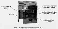
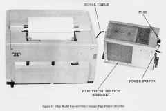
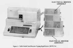
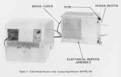
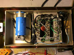
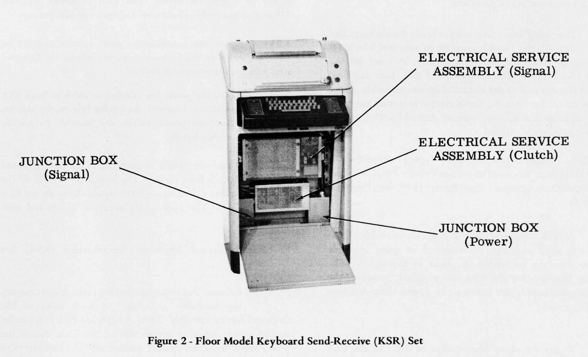
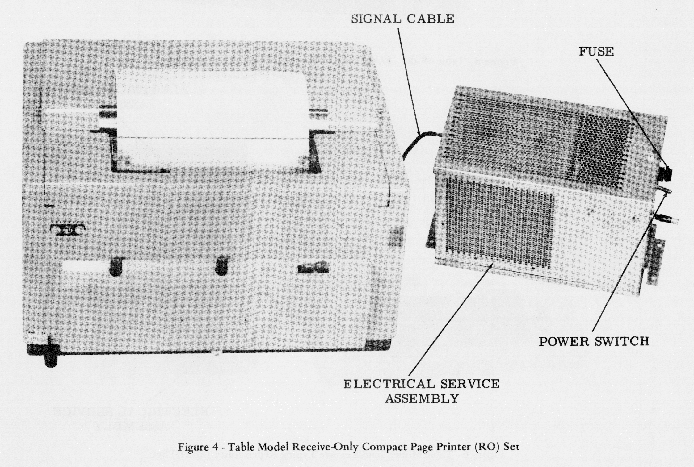
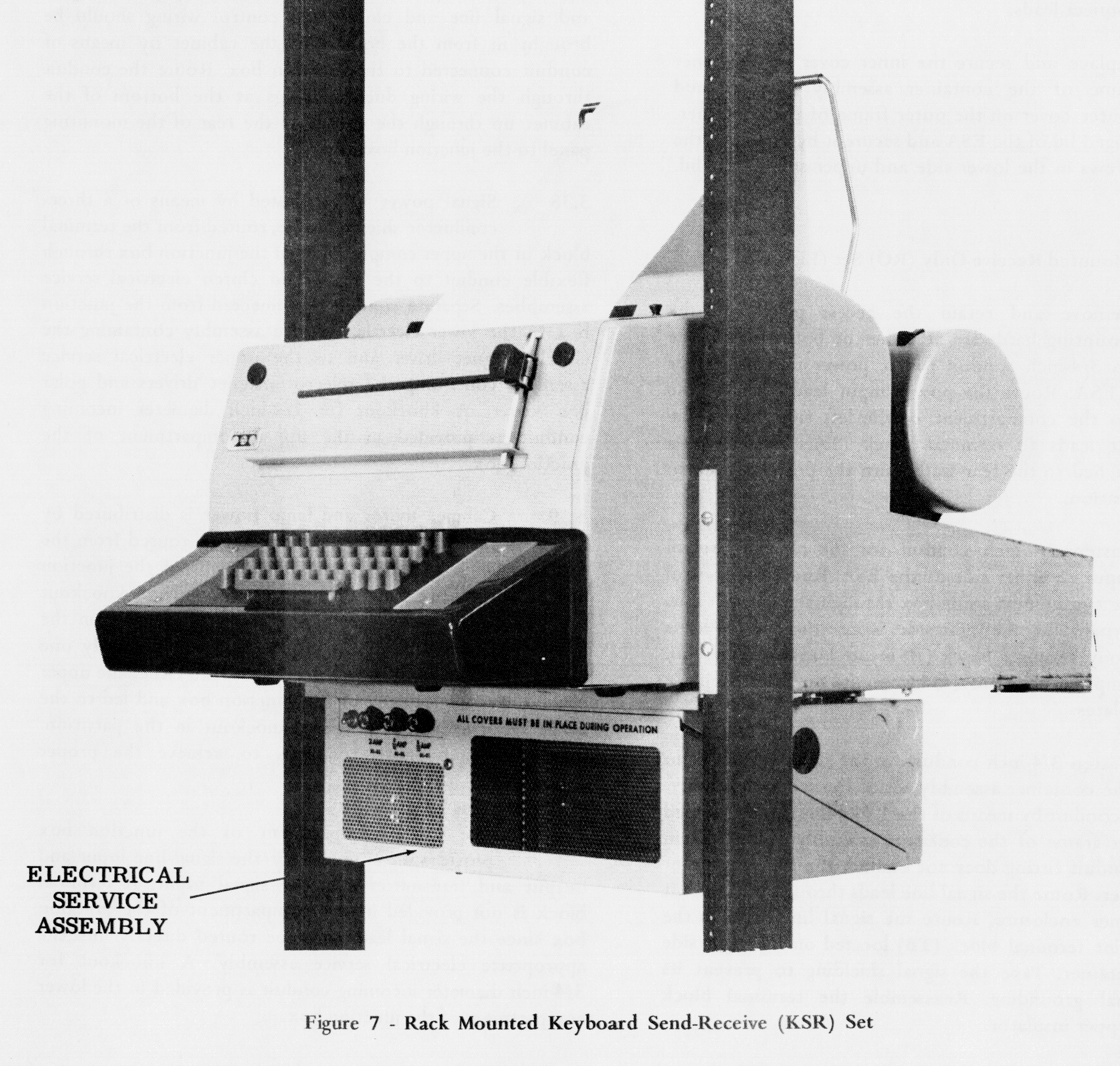
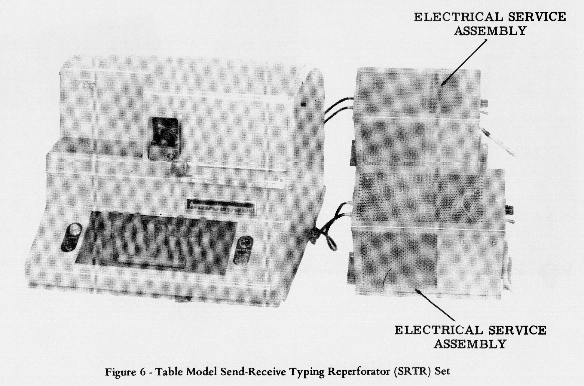
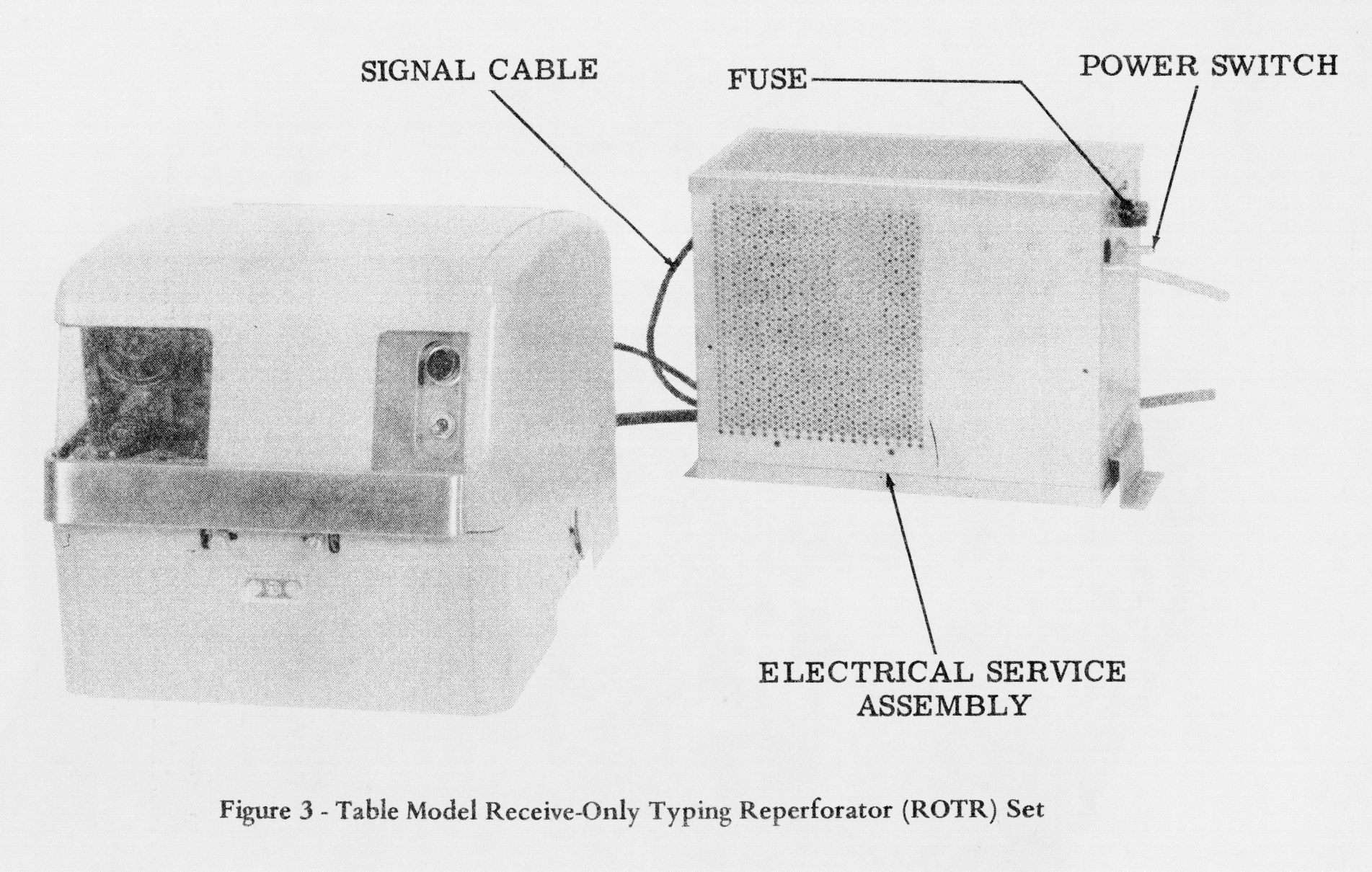
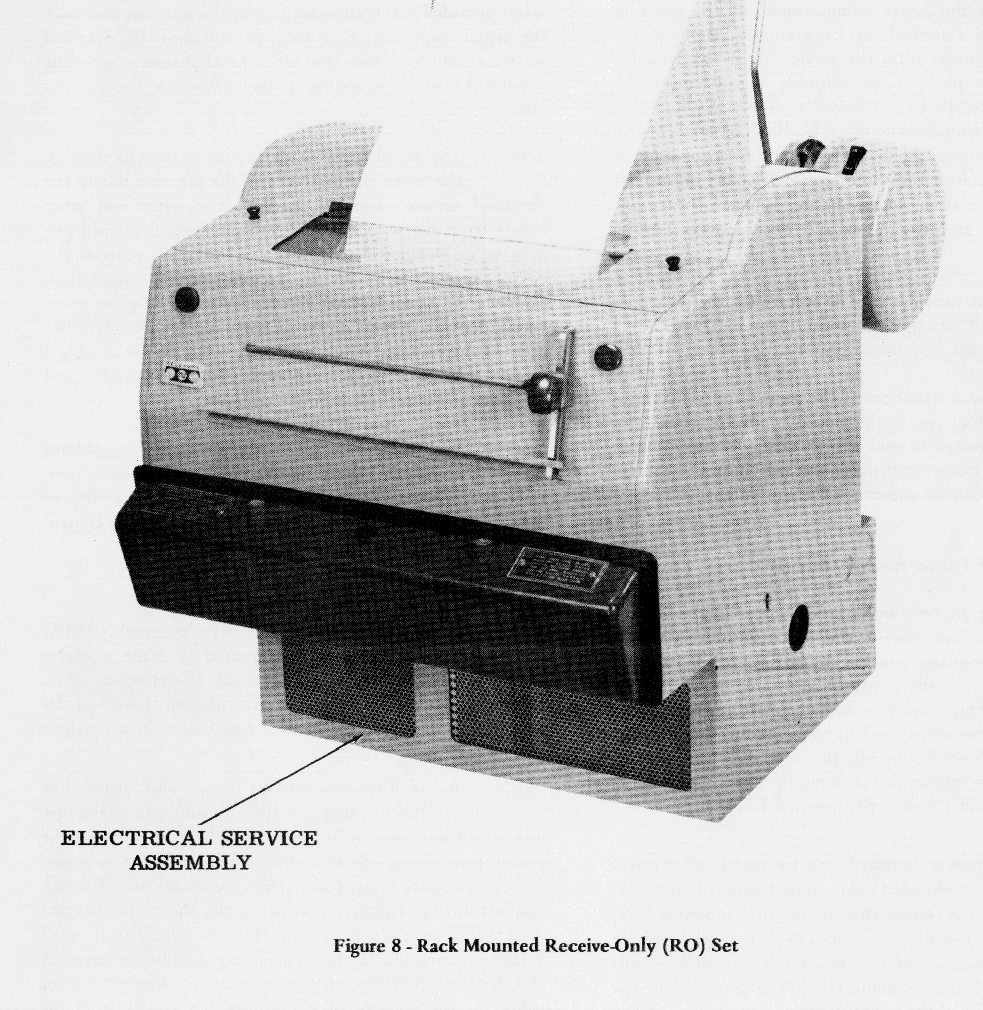
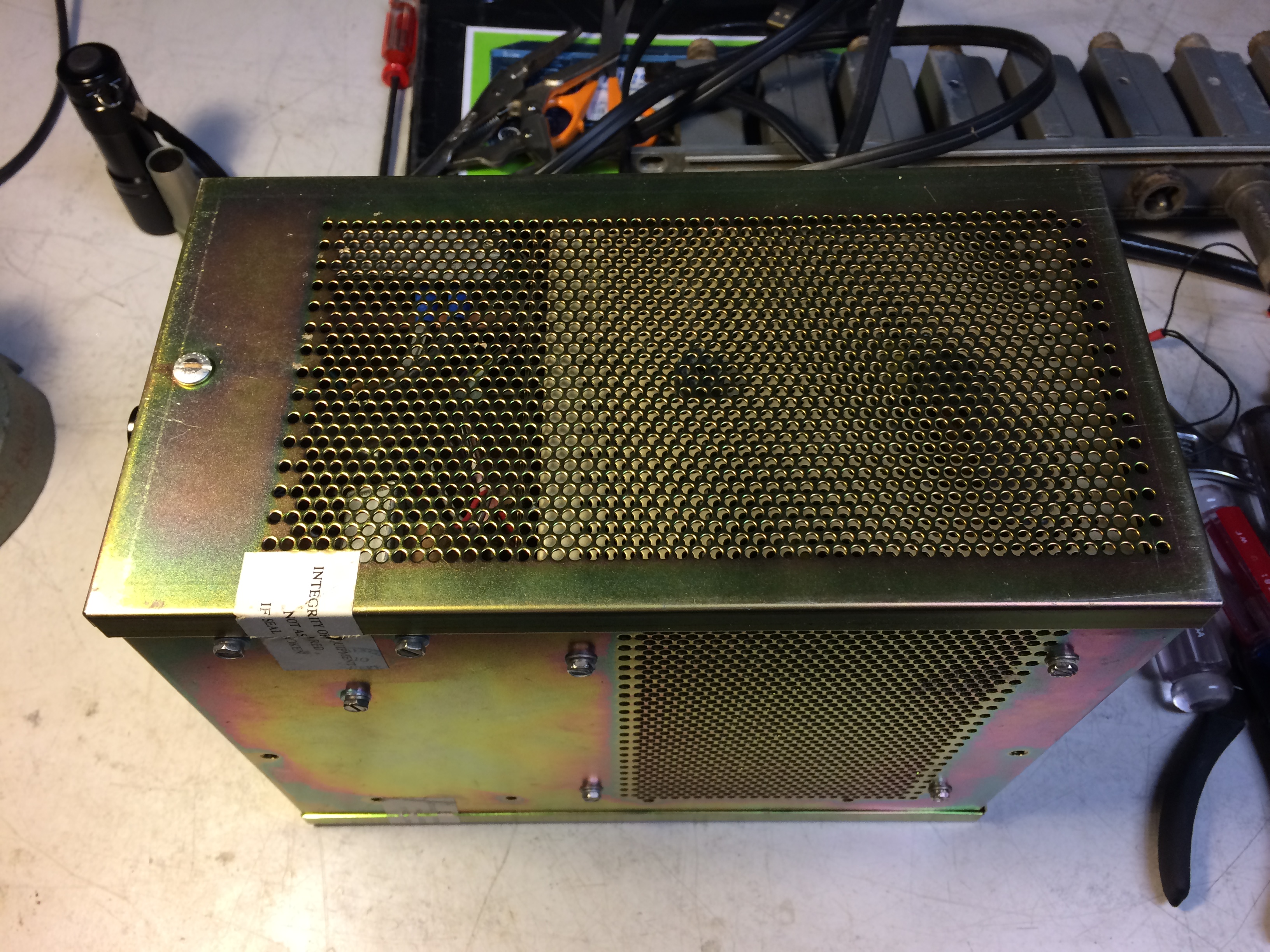
ELECTRICAL SERVICE ASSEMBLY
An external Electrical Service Assembly will contain a Selector Magnet
Driver (SMD) for converting +/-6v external signaling to 60ma to
drive the selector magnets of a typing unit or reperforator via a double
shielded cable. The Electrical Service Assembly will contain a Low Level
Keyer (LLK) for converting 28 keyboard or TD spacing contact closures (or
250ua photoelectric signals from a Compact KSR) to +/-6v external
signaling. The Electrical Service Assembly will also contain Clutch Magnet
Drivers (CMD) as needed for keyboard and TD sets. |
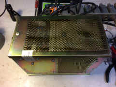
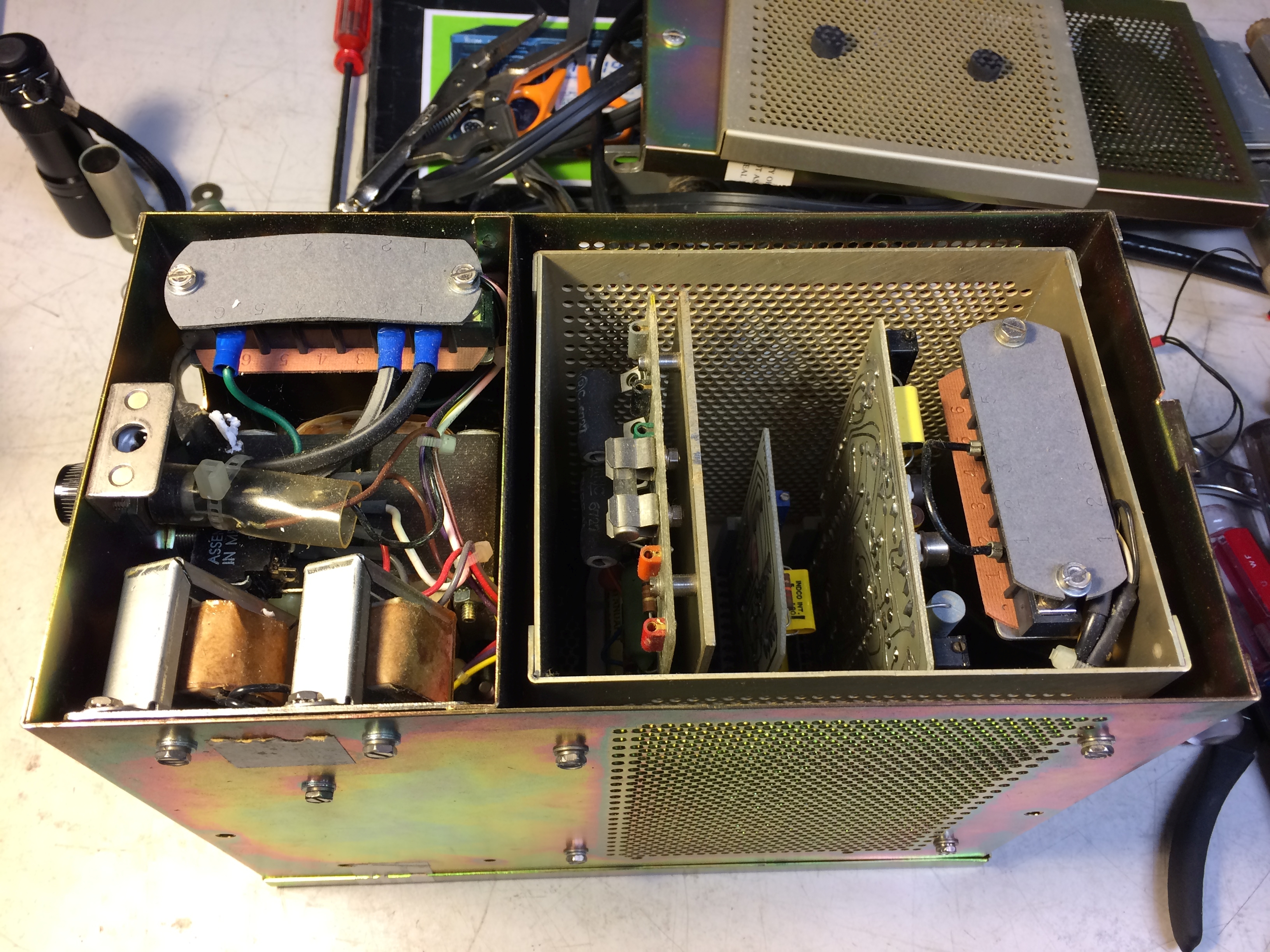
ESA Electronic Service Assembly
(outer shield)
 |
ESA Electronic Service Assembly
(inner shield)
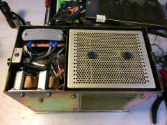 |
ESA Electronic Service Assembly
(card slots)
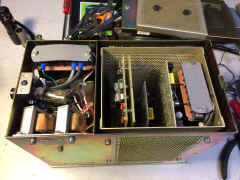 |
ESA Electronic Service Assembly
(bottom)
 |
|
The RFI signal generator contact box is composed of two metallic
boxes. An inner box completely enclosed by an outer box. The two boxes are
mechanically fastened together with fiber hardware and insulating material to
electrically isolate each box from the other.
The contact assembly is provided with gold-plated contacts for
low voltage operation. The assembly is enclosed within and electrically
insulated from the inner box. The filter card assembly is mounted to and above
the contact assembly. The filter is a network of three resistors and a capacitor
mounted on a circuit board. When used in conjunction with associated shielded
cables, power supplies, and keyer the filter provides a low-level interface and
RFI suppression.
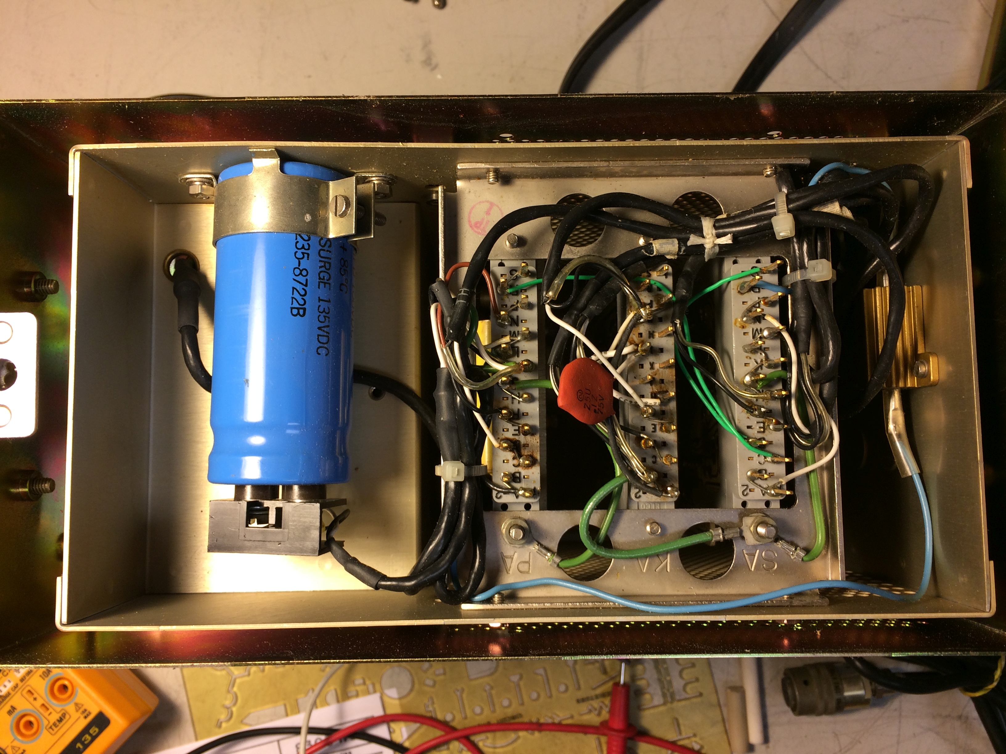
A double shielded cable assembly is provided to electrically
connect the contact box to a three-pin electrical receptacle. The shielded cable
is composed of three electrical conductors encircled by braided inner and outer
shields. Two of the three internal wires are electrically insulated and transfer
the telegraphic signals to associated equipment. The remaining wire is bare and
electrically connected to the inner contact box, inner braid shield, and cable
receptacle. The inner and outer braided shields are electrically separated from
each other and the wires by flexible solid dielectric. The inner braid is
electrically connected to the inner contact box and the outer braid is
electrically connected to the outer contact box. The cable assembly provides RFI
suppression when used with associated RFI equipment.
The 303142 LLK (Low Level Keyer), when used in conjunction
with the 321268 filter card assembly, is intended for use with the 323644
and 323645 signal generator (one contact) assemblies. This LLK is adaptable to
various types of 28 type equipment when used with the applicable ESA and is
designed to operate from one set of contacts. Two signal generator outputs
(filter card outputs), however, may be paralleled to drive one signal line from
either of two signal generators.
|
LOW-LEVEL (RFI) COMPACT SEND-RECEIVE (KSR) SET 28/32 KEYBOARD (AN/UGC-77)
- Schematic
The signal generating mechanism utilizes photoelectric cells
instead of a contact mechanism to generate a signal. A lamp assembly provides
the necessary light source to electrically activate the cells. A mechanical
shutter assembly, linked with the keyboard codebars and located between the
photocells and lamp assembly, provides windows to either allow light from the
light assembly to pass and activate the cells (mark) or block the light and not
activate the cells (space). The photocells will generate a parallel electrical
signal of approximately 300 microamperes (ua). The generated signal travels
along a shielded cable to a photoelectric distributor. The photoelectric distributor
serializes the signal, and by means of shielded cables, routes it to the input
of a polar line keyer.
The 323130 LLK (Low Level Keyer) is for use in photoelectric
systems (such as 28/32 keyboard) requiring a low-level interface and extreme RFI
suppression.
The 323130 keyer takes a 250 ua (min) photocell signal from
the distributor and by means of passive and active filtering, shapes the output. It is used in conjunction with a
333069 CMD (Clutch Magnet
Driver).
In the marking state (photocell illuminated), Q5 is turned off
causing the bases of Q1 and Q2 to go positive through the passive shaping
network made up of R2, Cl and R4. With the bases of Q1 and Q2 positive, Q1 will
turn on turning Q4 off and Q2 will turn off turning Q3 on. Capacitor C2,
resistor R6, R9, and capacitor C 3 further shape the wave by providing feedback
and phase shift thereby controlling the rate at which the active filter Ql, Q2,
Q3, Q4 will switch.
In the spacing state (photocell dark), Q5 is turned on providing
a negative signal to the bases of Q1 and Q2. The switching occurs as above
except, transistors that are off turn on and those that are on turn off.
During the transition from on to off and off to on, one of the
output transistors of the active filter is always conducting. This will provide
a smooth transition from plus volts through 0 volts to minus volts and back
again. The rate of switching being controlled by the feedback and phase shift of
C2, R6 , R9 and C3.
Diode CR1 compensates for the non-symmetry of the first stage.
Resistors R10 and R5 and capacitors C6 and C7 provide for the proper output
impedance and some additional shaping.
|
keyboard lamps, shutters, & photocells

|
distributor lamps and photocells
|
distributor and clutch on gearshift shaft

|
distributor slots for serialization
|
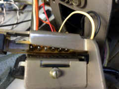
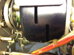
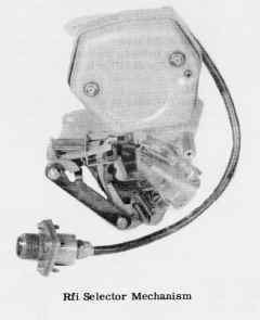
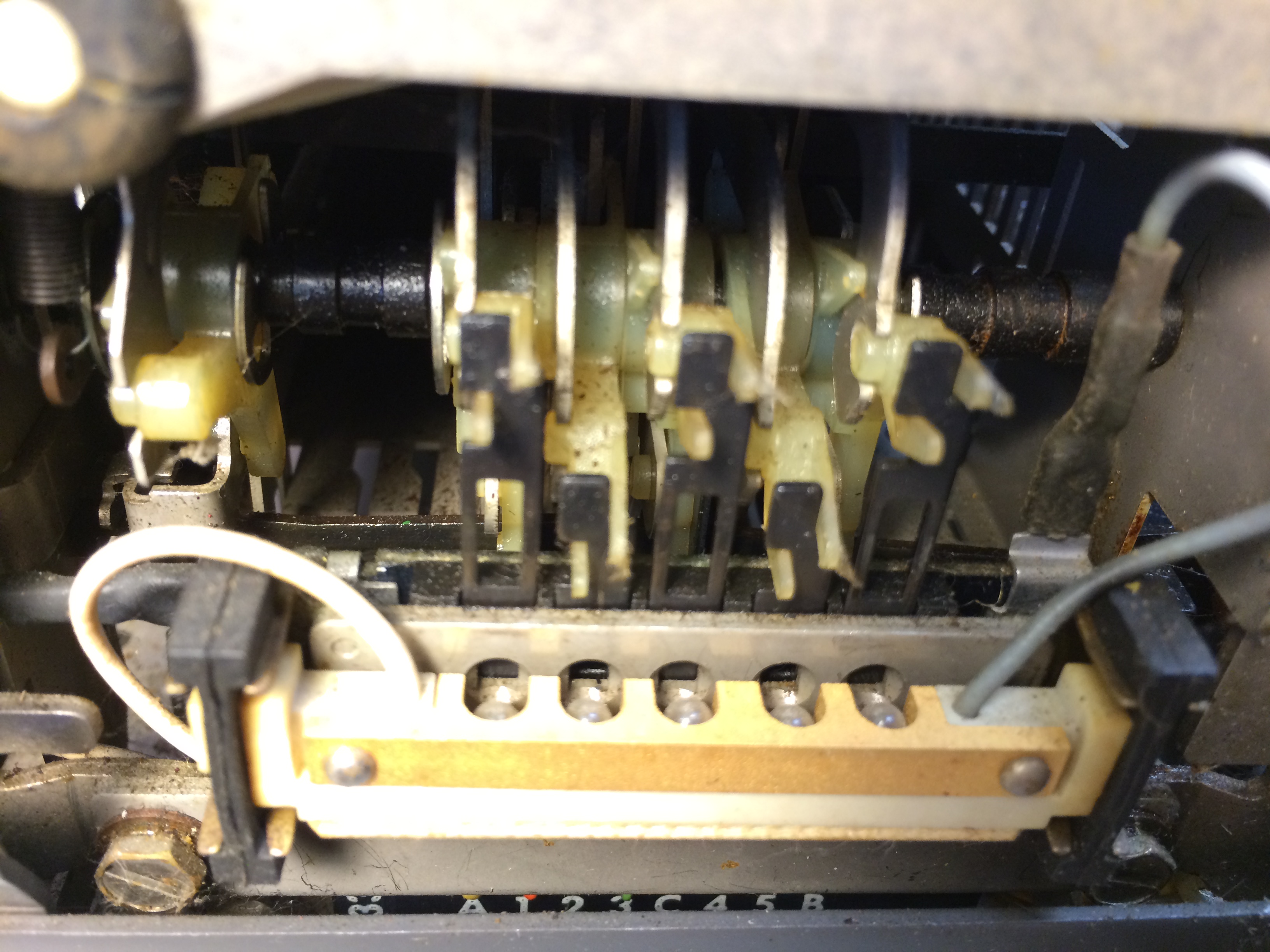
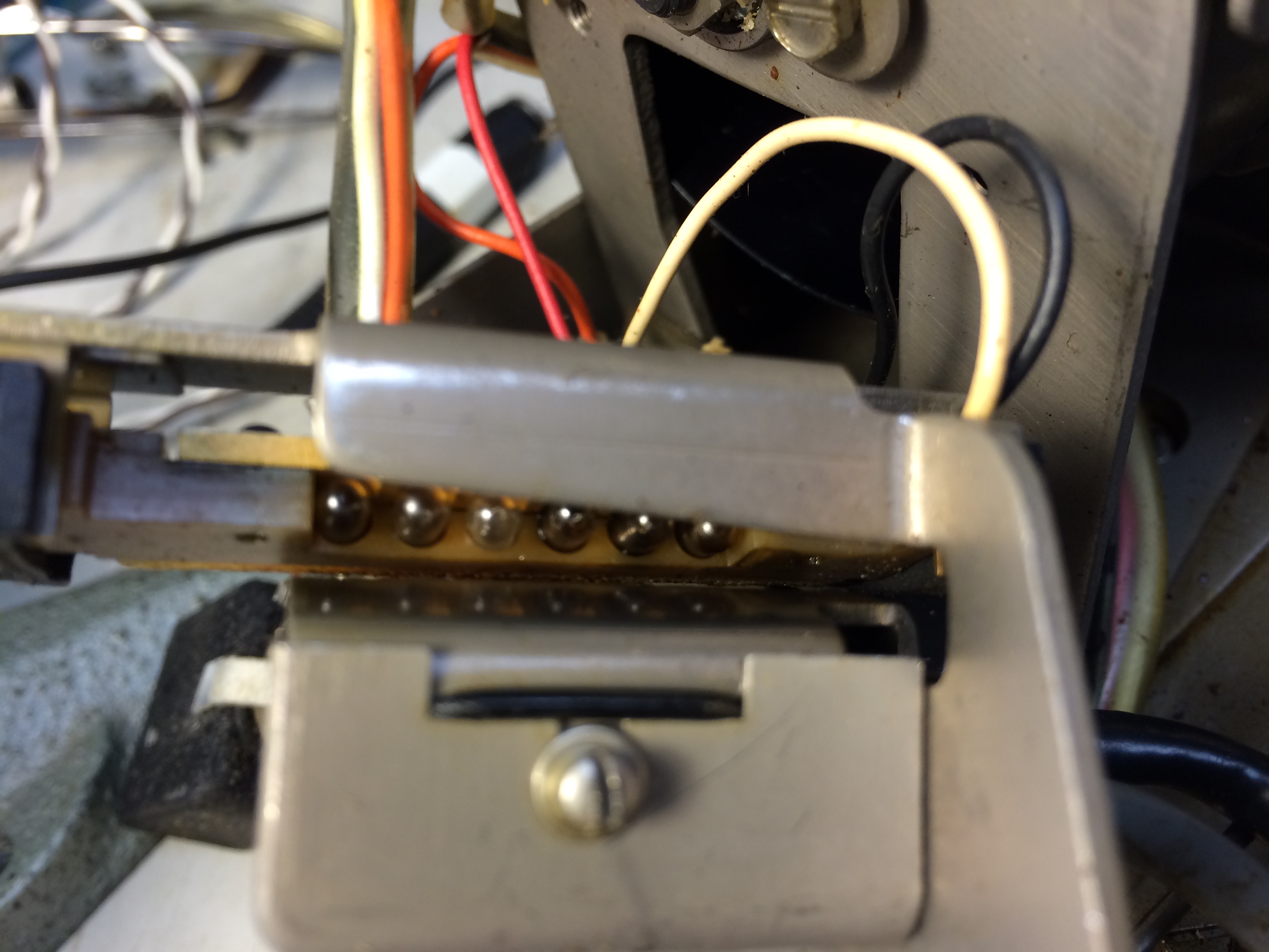
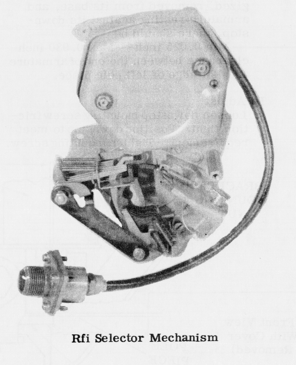
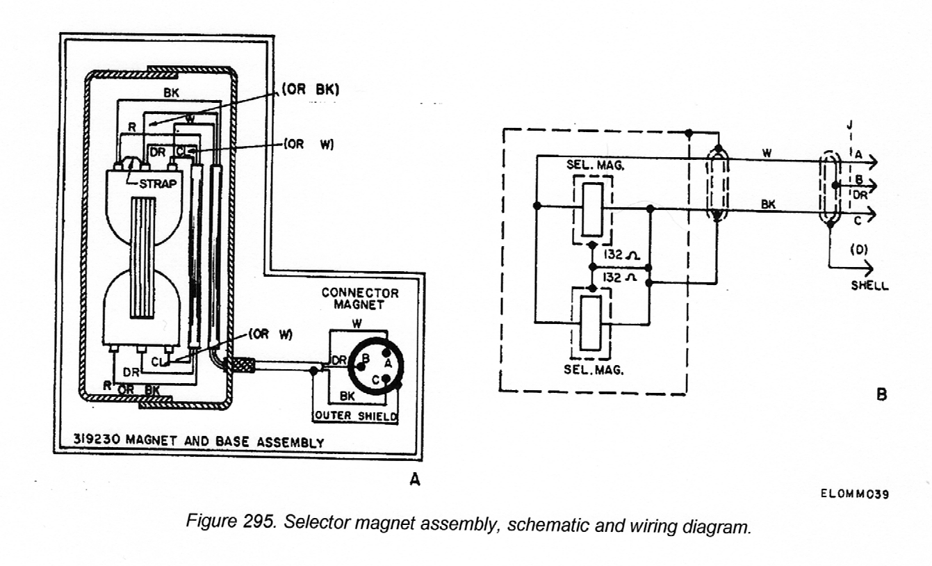
LOW-LEVEL (RFI) 28 SELECTOR MECHANISM FOR TYPING UNITS AND
REPERFORATORS
The RFI selector mechanism mounts on the upper right side frame
of the typing unit or the main frame of the reperforator. The selector consists
of a special three-pin electrical receptacle, double shielded cable and metallic
container.
The three-pin electrical receptacle insures a secure and
shielded electrical connection to other associated apparatus,. The double
shielded cable electrically connects the three-pin electrical receptacle to the
selector magnets. The shielded cable is composed of three electrical conductors
encircled by braided inner and outer shields. The inner and outer braided
shields are electrically separated from each other and the three electrical
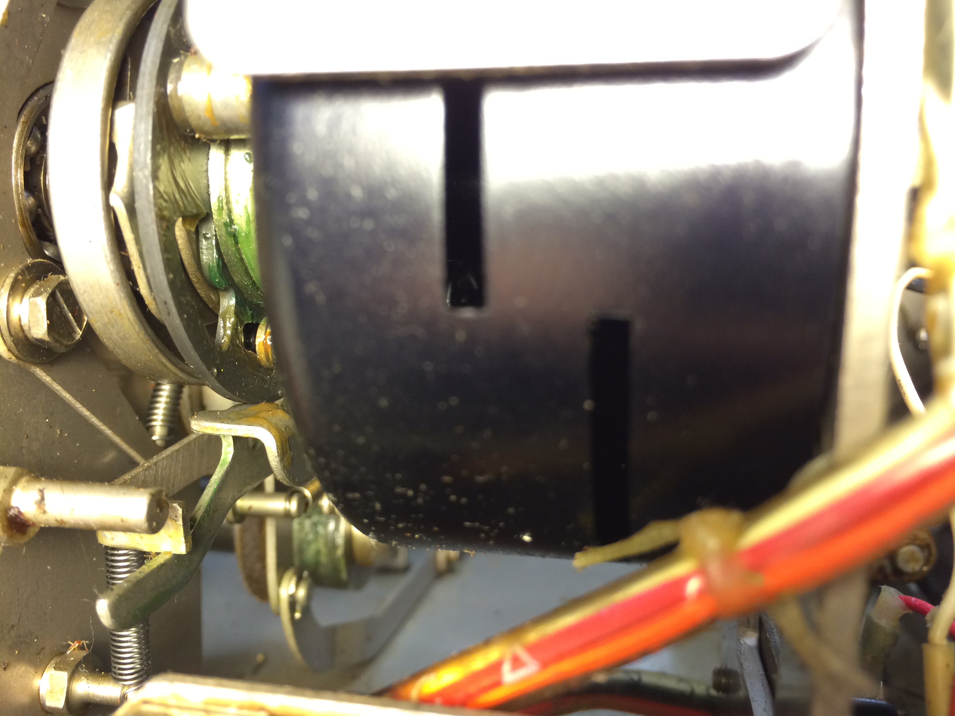
conductors by flexible solid dielectric. The metallic container functions as a
shielded enclosure for the selector magnet assembly.
Enclosed within the metallic container are the selector
magnet coils, coil mounting bracket and selector armature. Each selector magnet
coil contains an electrostatic shield which surrounds the coil windings. The
selector coil mounting bracket provides mounting facilities for the coils, armature, and biasing spring. The receptacle, shielded cable, metallic container,
and selector coils provide RFI suppression when used with associated RFI
equipment.
|

|
LOW-LEVEL (RFI) 28 SELECTOR MAGNET DRIVER SMD Schematic, SMD
Card
The input current to the 323810 selector
magnet driver (SMD) is a low level +6 volt for a
marking state, and a -6 volt for a spacing state.
The output current of the SMD is 60 mA +/-10%
during the marking state. The output is zero during
the spacing state. Overall receiving margins of properly adjusted
28 type selectors driven by this SMD (polar
rectangular wave input) should exceed 70 points at
either input. The SMD operates at bit rates up to
75 baud.
The SMD assumes the marking state with
positive input voltages not greater than 0.5
volt and the spacing state with negative voltages
not greater than 0.5 volt. The marking and spacing
switching levels are adjustable within 10% of each
other. This requirement applies to either input.
Each input of the SMD has a minimum input
resistance of 50,000 ohms. The maximum input
capacitance of either input is 2500 picofarads.
The SMD provides two inputs and makes possible reception from
either one of two separate transmitters (single input operation) while the input
line from the other transmitter is open. A spacing signal at either input will
provide a spacing output. The SMD provides a marking
output when both inputs are open. Both
inputs cannot be in the marking condition
simultaneously without producing a garbled output.
|
AN/UGC-77 Information Page


