AN/FCC-3 TTY Multiplexer - Wanted
|
I am trying to get at least one transmitter-receiver pair to work, so I need
matching filter frequencies or matching units.
Please send e-mail if you have any
of these filters or any units of AN/FCC-3
The FCC-3 has 8 Narrow channels and 4 Wide channels
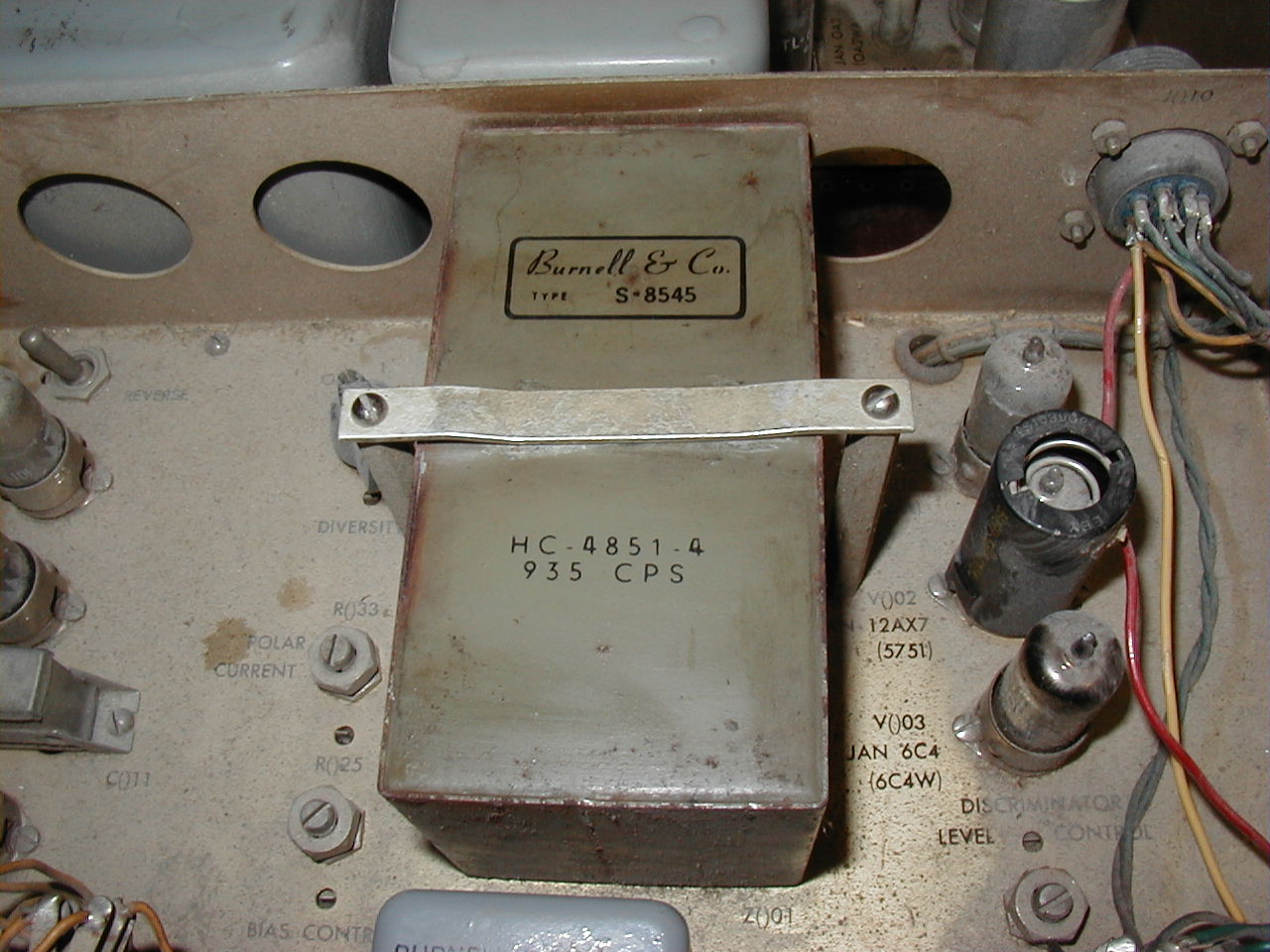
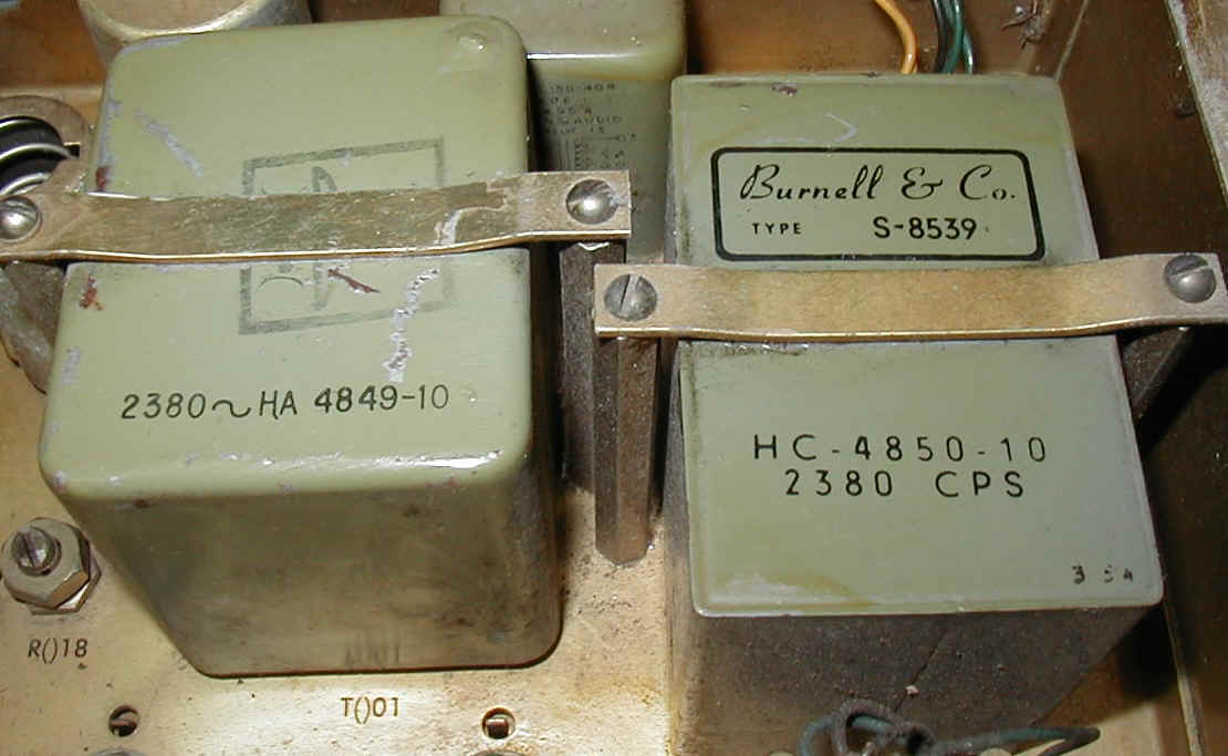
Filters are made by Burnell for 425, 595, 765, 935, 1105, 1275, 1445,
1615, 1955, 2380, 2805, 3230 cps (Hz)
|
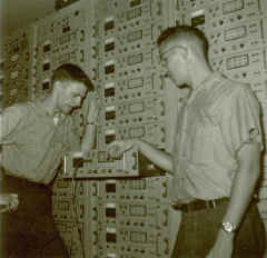
AN/FCC-3 systems at NAVCOMMSTA Puerto Rico, 1958 |
"DATA SUPPLIED ON RADIO AND TELEGRAPH EQUIPMENT"
By Charles H. Davis, Electronics Shore Division, Bureau of Ships
BuShips Journal Dec 1954
The following descriptions of the Navy Model UQ Radio Relay Link equipment and the types AN/FCC-3,
-7, and -8 Telegraph Carrier Terminal equipment are published for general information and advance planning by field activities, pending distribution of instruction books.
While the AN/FCC-3 equipment eventually will replace obsolete telegraph carrier terminal equipment presently in use, it is not to be considered an integral part of the UQ Link system and will be treated as an independent allowance item. In many instances the AN/FCC-3 equipment will be assigned to communication facilities well in advance of the microwave link equipment.
[See here for the UQ portion of this article]
TELEGRAPH CARRIER TERMINAL AM/FCC-3, -7, AND -8 AND TELEPHONE TERMINAL TA-269/U
The AN/FCC-3 is a combined narrow- and wide-band telegraph terminal equipment which may be operated over any good quality voice channel radio link or wire line, having a loss not exceeding 30
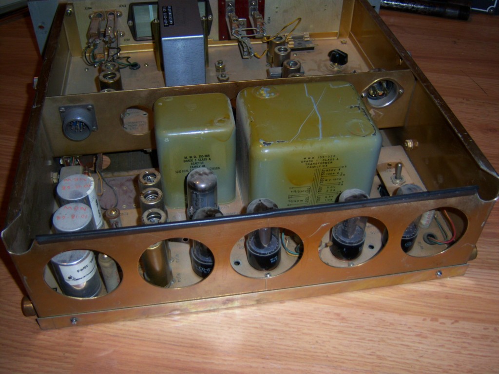
dbm. The equipment is housed in two relay rack cabinets of the same construction and dimensions as the Cabinet CY-597/G but with minor internal modifications. One cabinet contains the transmitting group or sending equipment and the other cabinet, the receive group or receiving equipment.
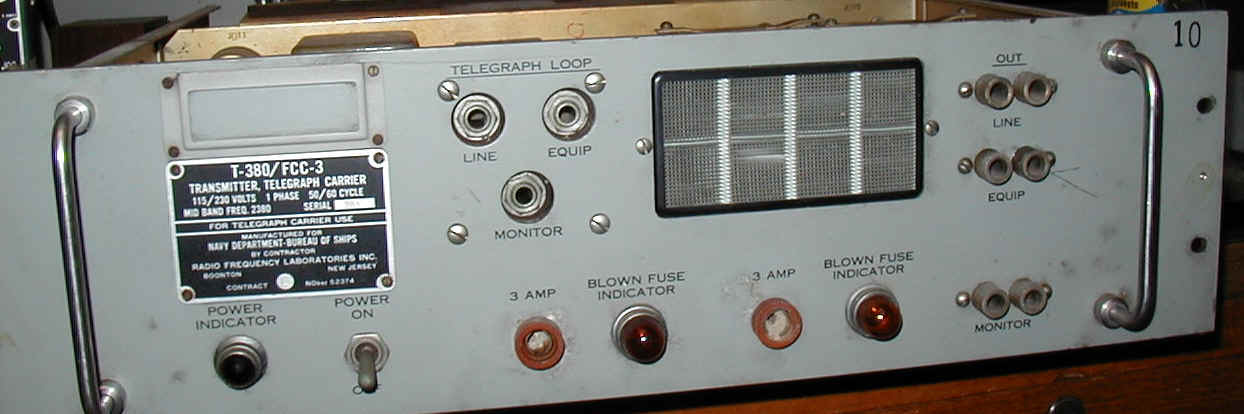
The transmitting group consists of eight narrow-band, 85-cycle, frequency-shift channel oscillators and four wide-band, 170-cycle, frequency-shift channel oscillators. The narrow-band oscillators have mid-band frequencies between 425 and 1615 cycles per second, and 170-cycle separation between channels. The wide-band oscillators have mid-band frequencies of 1955, 2380, 2805 and 3230 cycles. The narrow-band channels are capable of handling a keying rate of 40 dot cycles per second; the wide-band channels, a rate of 100 dot cycles per second.
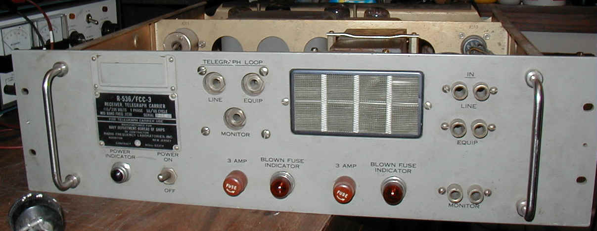
The channel oscillator (or transmitter) is keyed either from a 20 ma to 60 ma neutral telegraph loop with battery supplied from the loop or the transmitter, or from a 30 ma polar telegraph loop with battery supplied from the loop. The outputs from the transmitter of the AN/ FCC-3 equipment are combined for transmission over a single-voice channel having a nominal input impedance of 600 ohms.
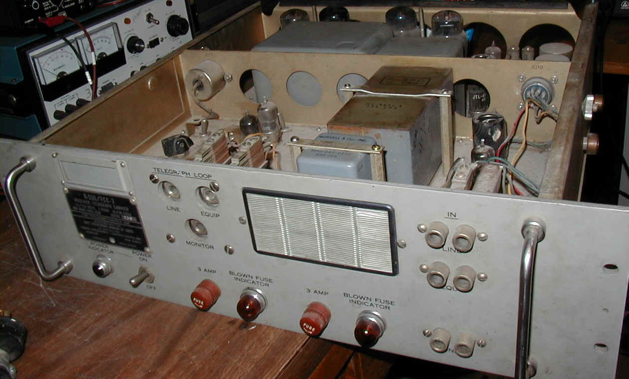
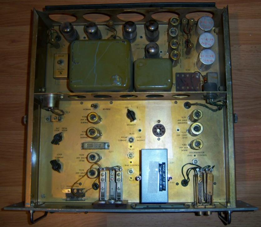
The receive group consists of eight narrow-band and four wide-band receivers (demodulators) which convert the tones to direct current for operating telegraph or teletype equipment. The d-c output is capable of keying a 20 ma or 60 ma neutral loop with battery supplied from either the loop or the receiver of the AN/FCC-3 equipment, or a 30 ma polar loop with battery supplied from the receiver of the AN/FCC-3. (Note: Neither side of the output circuit can be grounded, due to the keyer circuit of the receiver.)
Since the receiver output is designed for the control of current operated devices, receiver modifications have been approved tentatively in order to obtain a voltage output for operation of radio transmitter frequency-shift keyers or similar devices having one side of the input circuit at ground potential.
Frequency Converter CV-243/FCC-3 is provided in the transmitter group for translating the eight narrow-band channels to a frequency spectrum of from 1742.5 to 3017.5 cycles.
Electronic Frequency Converter CV-244/FCC-3 is provided in the receiver group for restoring the inverted channels to the proper frequencies before entry to the receiver input circuit. Using these converters, a total of 16 narrow-band telegraph channels may be transmitted over a single 3400-cycle voice channel. Operational planning does not include this method for general use in the AN/FCC-3 and utilizes this method only in special cases with the AN/FCC-7 and AN/FCC-8 equipments. Special connections are provided which permit the line amplifier section of the above converters to be used in lieu of external amplifiers for control of signal levels.
The AN/FCC-7 equipment consists of eight narrow-band channels and an electronic frequency converter. The AN/ FCC-8 consists of eight narrow-band channels without the converter.
The AN/ FCC-3 equipment will provide satisfactory operation over existing radio link systems (using the combination of Very High Frequency Radio Telephone Transmitting Equipment, TDG and Very High Frequency Radio Receiving Equipment, RBQ) which were marginal with the UN or similar single tone terminal equipment.
UN To Be Replaced
Plans are being made to replace the Carrier Control System UN (telegraph terminal equipment) with the AN/FCC-3 as equipment and funds become available. Replacement of the UN does not necessarily mean that the radio frequency link equipment, such as the TDG and RBQ, will be replaced at the same time.
The tone channels of AN/FCC-3 also are capable of being operated in frequency-diversity for use on long-haul radio circuits, thus making it comparable to the Two-Tone Carrier Control System UP. Then operated in frequency-diversity, the total number of channels is reduced from 12 to 6, since two channels are keyed simultaneously. Therefore, the AN/FCC-3 will be assigned as replacement for the UP equipment on single side-band circuits. The two-wire/four-wire voice terminal of the UP will be replaced by the TA-269/U equipment described in a following paragraph.
External wiring to the transmitting group normally requires a single-phase 115- or 230-volt, 1125-watt circuit for power, 12 signal circuits for d-c telegraph loops, and one audio signal circuit for the combined output of the transmitters. A similar number of circuits is required for the receive group. The power requirement of the latter is 1770 watts.
Individual Circuits Required
Type plans for installation, when completed by the Bureau, will require individual signal circuits from the audio output of each transmitter to a jack field or patch board in the supervisory area to facilitate testing and provide flexibility in the use of the equipment. Combining the outputs will be accomplished by strapping, located on the main distributing frame instead of within the terminal equipment cabinet. The total number of audio signal circuits required then becomes 15, including the input and output of the frequency converter. Similarly, the input to each receiver of the AN/ FCC-3 equipment will be terminated in the jack field in order that receivers may be removed from a circuit by patching.
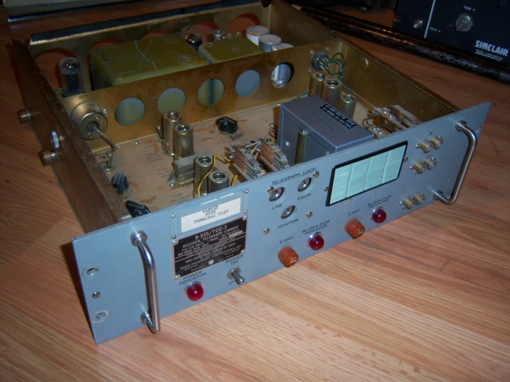
Each unit of the equipment, except the power distribution unit, is mounted on a drawer-type slide permitting the chassis to be pulled out and tilted, bottom side out, for servicing. The chassis may be removed from the cabinet by disconnecting the power and signal cable connectors and lifting it out.
The TA-269/U provides a terminus for the two-wire remote receive and the two-wire transmit circuits for extension, on a two-wire basis, to a local telephone switchboard. It is designed for rack mounting, is of the sliding-drawer type construction, and measures approximately 5 1/4 inches in height, 19 inches in width, and 16 inches in depth. The TA-269/U is not to be furnished as part of the AN/FCC-3, but will be considered as a separate allowance item.
AN/FCC-3 units are:
- CV-243/FCC-3 Electronic Frequency Converter (Receiver)
- CV-244/FCC-3 Electronic Frequency Converter (Transmitter)
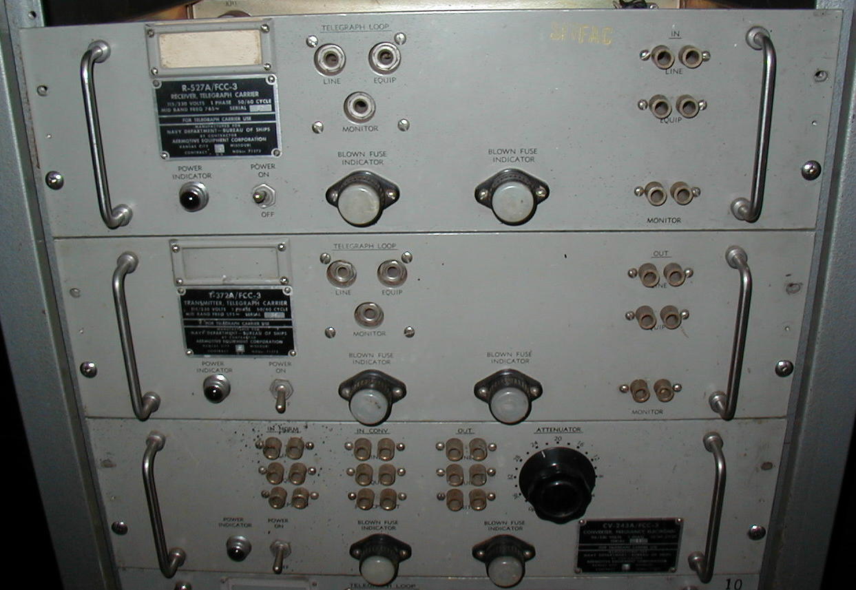
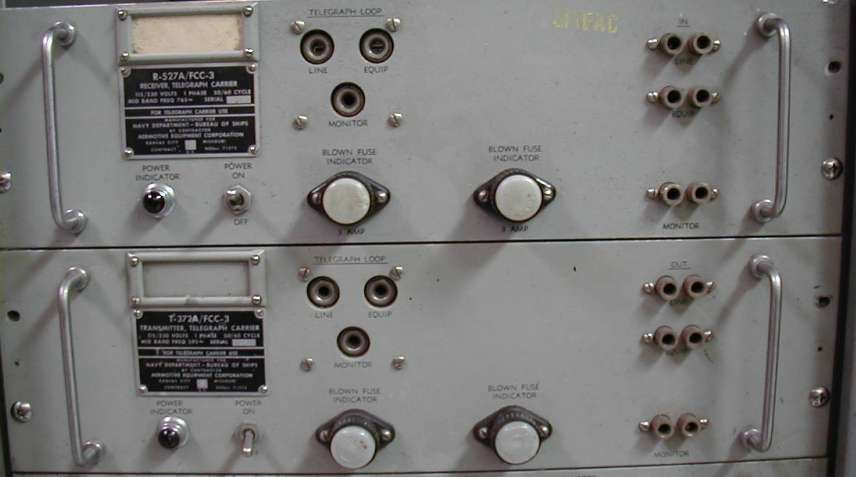
- R-525/FCC-3 Telegraph Carrier Receiver (425 cps, narrow)
- R-526/FCC-3 Telegraph Carrier Receiver (595 cps, narrow)
- R-527/FCC-3 Telegraph Carrier Receiver (765 cps, narrow)
- R-528/FCC-3 Telegraph Carrier Receiver (935 cps, narrow)
- R-529/FCC-3 Telegraph Carrier Receiver (1105 cps, narrow)
- R-530/FCC-3 Telegraph Carrier Receiver (1275 cps, narrow)
- R-531/FCC-3 Telegraph Carrier Receiver (1445 cps, narrow)
- R-532/FCC-3 Telegraph Carrier Receiver (1615 cps, narrow)
- R-533/FCC-3 Telegraph Carrier Receiver (1955 cps, wide)
- R-534/FCC-3 Telegraph Carrier Receiver (2380 cps, wide)
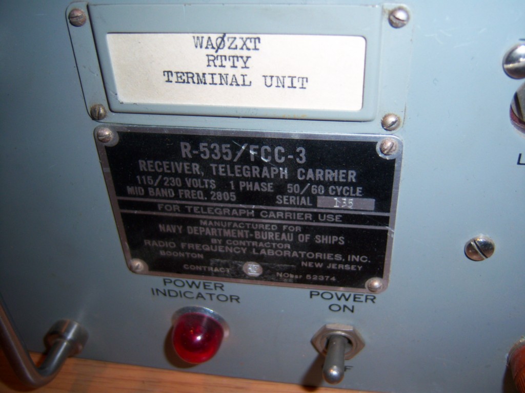
- R-535/FCC-3 Telegraph Carrier Receiver (2805 cps, wide)
- R-536/FCC-3 Telegraph Carrier Receiver (3230 cps, wide)
- T-371/FCC-3 Telegraph Carrier Transmitter (425 cps, narrow)
- T-372/FCC-3 Telegraph Carrier Transmitter (595 cps, narrow)
- T-373/FCC-3 Telegraph Carrier Transmitter (765 cps, narrow)
- T-374/FCC-3 Telegraph Carrier Transmitter (935 cps, narrow)
- T-375/FCC-3 Telegraph Carrier Transmitter (1105 cps, narrow)
- T-376/FCC-3 Telegraph Carrier Transmitter (1275 cps, narrow)
- T-377/FCC-3 Telegraph Carrier Transmitter (1445 cps, narrow)
- T-378/FCC-3 Telegraph Carrier Transmitter (1615 cps, narrow)
- T-379/FCC-3 Telegraph Carrier Transmitter (1955 cps, wide)
- T-380/FCC-3 Telegraph Carrier Transmitter (2380 cps, wide)
- T-381/FCC-3 Telegraph Carrier Transmitter (2805 cps, wide)
- T-382/FCC-3 Telegraph Carrier Transmitter (3230 cps, wide)
- 2 ea CY-1196/FCC-3 Telegraph Carrier Terminal Cabinet.