|
I am pretty handy with a soldering iron and a schematic
diagram, but I hate painting etc. so I try to stick with
equipment that doesn't require much more than cleaning to
become aesthetically acceptable. I try to restore
everything I have to working condition, with the rare
exception of something so historically significant that it
should be left untouched. This is part of the living
history concept, that things must do, not just be.
Receivers
RAL
RCA-built CRV-46156, the first of the line was contracted
for in 1935. Though largely replaced by the later RBA,
RBB, and RBC receivers, the RAL and its LF mate the RAK were
still put to use on many vessels during WWII. They were
used extensively on submarines. MASSACHUSETTS has a
RAK/RAL pair in Radio Central and another pair in Radio
III. Most of the other LF/MF/HF
receivers are the RBA, RBB, and RBCs.
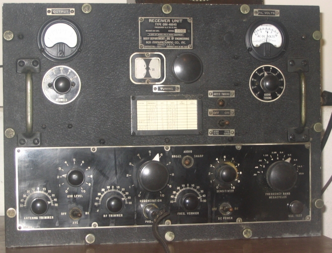
The RAL covers 300Kc to 23Mc. It has 2 RF stages
and a regenerative detector. I find it to be plenty
sensitive, at least on 7Mc where I have used it most, but it
is lacking in selectivity. The lack of RF selectivity is
somewhat compensated for by a narrow audio
filter. The RAL is quite stable, and I have
been able to make contacts on single sideband on 14Mc using
it.
|
| RAL-5 serial
number 500 |
|
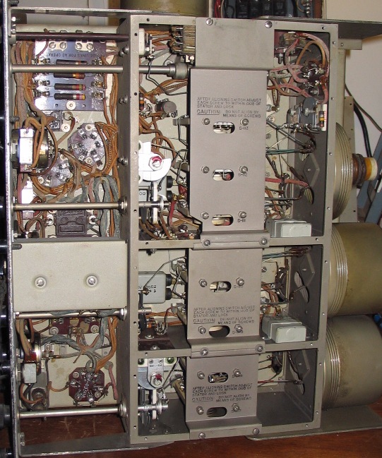
| Bottom of
RAL-6 |
RAL-6 with shield open to clean
bandswitch. The uppermost shaft in the picture above
drives the bandswitch shaft through a right-angle drive.
The lower frequency coils are in the round cans on the right,
the topmost one being removed.
|
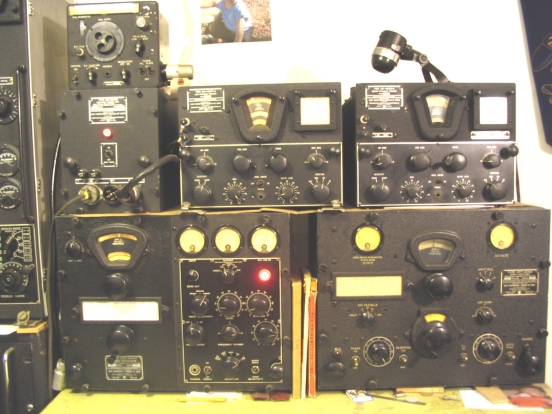
| Top:LM, RBM
PS,RBM(HF),RBM(MF). Bottom:RBB,
RBA |
RBA-1
This RBA-1, CFT-46154 was built by Federal Telegraph
in Newark, NJ and covers 15-600Kc. It is a Tuned Radio
Frequency (TRF) design with a heterodyne oscillator for CW
reception.
The calibration chart lists the following stations:
NSS F 18.6kc (Arlington)
NAA F 15.5kc
NSS B 122kc
NBA F 32.6 (Panama)
NBL 450kc
GYU, GYW (Gibralter)
This list of stations suggests that this receiver was
installed on a ship serving in the Atlantic.
RBB-1
RCA-made CRV-46147 receiver, covering .5 to 4Mc.
CRV indicates RCA manufacture. 46xxx indicates a
receiver. You will see this pattern in the rest of the
gear. Weighing in at 82 pounds, this is a really rugged
and high-performance receiver. This receiver and its
brother the RBC were conceived and brought to manufacture in a
rapid fashion right before the war, when the Navy realized
that the RAK/RAL were not up to par. MASSACHUSETTS
carried RBC serial numbers 4 and 6, and RBB number 5.
RBB and RBC are single-conversion superhets with 400kc IF
frequency. The narrow bandwidth position is 1kc
wide. For AM or MCW use, an AVC function is
available. CW signals are held at a constant output
using an output limiter.
RBC-1
CRV-46148 covering 4.0 to 27Mc.
Click here to read more
about military radio equipment built by RCA.
RBM
Shown above are: CAY-46077-A RBM-5 High Frequency
Receiver
CAY-46076-A RBM-5 Medium Frequency Receiver
CAY-20086
Rectifier Power Unit.
CAY indicates Westinghouse manufacture.
These semi-portable receivers were designed for advanced
base operations along with the TBW transmitter. They
could also be powered by a dynamotor supply.
A closely-related receiver is the RBS, electrically
identical to the RBM HF unit, which was used for
monitoring(bridge of Battleship) and backup purposes on
ships. The Lionfish carries two RBS
receivers. RBS is designed to mount on a
table. The RBM has a waterproof carrying case that is
set up as a portable operating position with legs and using
the case lid as a desk. Both the MF and HF receiver fit
in one case, the same size as the ones the TBW units travel
in.
The LM frequency meter pictured on top of the Rectifier
Power Unit is used to calibrate the RBM and TBW.
RBK
The RBK-1, also known as a
Hallicrafters S-27, covers 27 to 143 Mc, AM/FM/CW.
It has narrow(10-ish Kc) and wide (100-ish Kc)
bandwidths. I have used it to work ham AM on 10m, listen
to CBers, play 93.3Mc FM loud on the speaker, monitor aircraft
on 130Mc AM, and listen to low-band TV sound.
The Navy called it a "monitoring"
receiver. It could be used to monitor formation
communications by TBS, monitor aircraft traffic, and for
interception of enemy communications.
The RBK-1 was equipped with an IF output for
an RBW panoramic adaptor, which displayed a 1 Megacycle wide
spectrum for quickly finding signals. The RBK/RBW
combination was found in the Combat Information Center on many
combat vessels.
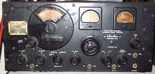
|
| RBK-1 |
TBS
The TBS is a transmitter-receiver pair that operates from
60 to 80Mc AM. The receiver is a superhet with an IF of
5.3Mc. The transmitter puts out 50W from an 808
modulated by a pair of 808s.
The TBS, originally contracted for in 1938, uses a
mixture of big-pin and octal tubes. It operates on one
crystal-controlled channel. It greatly simplified
tactical communications in a convoy, especially when
visibility made flag or blinking light communications
difficult. Those methods were slow even under the best
of conditions. While TBS is not officially an acronym
for "Talk Between Ships", that describes its function well.
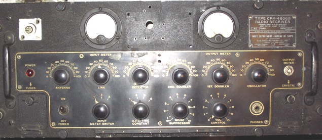
|
| TBS-3 Receiver
CRV-46068 |
|