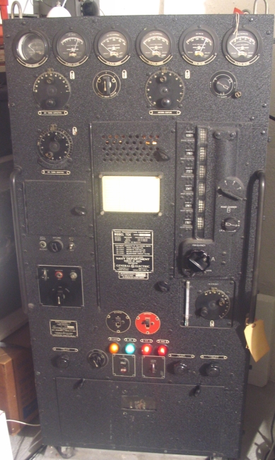
World War II Navy Radio
My Transmitters
Home | The Radioman's Job | My Receivers | Mill | Point to Point | My Transmitters | Remote Control | Radiotelephone | Portables | Test Equipment | Frequencies | Training | Procedures | Museum Activities | Museum Ships | On the Air Activities | Navy Television | Men Who Lived It | Resources | Hints and Kinks | Nancy(Infrared) | Wanted | Contact Me

NOTE - This is a re-creation of Rob Flory's original site which crashed some time ago - unfortunately some photos are still missing but most of the text is here - if you can help with any replacement photos, please send e-mail to Rob or to
Nick K4NYW

Click here for Nick's 1950's-60's Navy Radio Pages -  www.navy-radio.com

Transmitters

TBL
 
Click the link below to go to the page about my TBL transmitter.
 
TBL 

TDE
 
Click below to go to the page about my TDE transmitter.
 

TCK
 
The TCK uses an 837 Master Oscillator, 837 Intermediate Power Amplifier and parallel pair of 813s as Power Amplifier.   Power output is rated at 400W CW and 100W AM.  The master oscillator is contained in a thermostatically-controlled heated box kept at 60 degrees C.  It contains its own crystal frequency calibrator which allows calibration at 100kc intervals.  A unique feature of the TCK is its direct frequency readout. 
 
On CW, the TCK uses cathode keying by a keying relay.  On AM, the final amplifier is grid modulated with an 807, which is why its output is limited on AM.  It is used with a carbon microphone on AM.
 
The recording below was made by NI9Y(Thanks!) on 3.5Mc.  The rapid fading is due to auroral conditions at the time.
 
My TCK is serial number 14, a very early one, with a delivery date in 1943, so it came along later in the war.  It seems to me to be intended as a replacement for the TBK, as its frequency coverage and power level are very similar.
 

TCK recorded by NI9Y

tck.jpg
TCK Transmitter

unicontrol.jpg
TCK Uni-Control

The TCK's Uni-Control adjusts the frequency of the Master Oscillator.  All the other tuned circuits in the Intermediate Power Amplifier and Power Amplifier track with the frequency in contrast to older transmitters like the TBK, which has separate controls with logging scales for each tuned circuit.  To change frequency with the TCK, the operator need only tune the Uni-Control to the desired frequency, adjust IPA and PA trimmers, and tune the antenna circuit.

TBW
 
To call what I was using a TBW is a slight misnomer, as all I was using is the CAY-52239 HF module.    The  set is designed for forward base use, and travels in waterproof containers. 
 
The TBW runs on 800-cycle power, which is normally provided by a generator.  This not only lightens the power supply components, but facilitates plate keying of the transmitter.  I replaced the power supply and generator with a power supply and keying unit that tried to duplicate the original operating conditions as much as possible. 
 
The keying relay in this transmitter is fun, drawing a whopping 3 Amps at 12 Volts.  One contact(K-301B) on the relay grounds the cold end of the grid leak on the master oscillator(M.O.) and intermediate amplifier(I.A.).  Another contact(K-301A) applies the 120V 800-cycle power to the primaries of the high voltage supplies for the power amplifier and the I.A. and M.O.  Adequate filtering can be had with 800-cycle power, using only a 1uF filter, which charges rapidly.  Since primary keying of a 60-cycle power supply is not feasible at reasonable keying speeds, I keyed the D.C. voltage instead of the primary, using  high voltage relays, and a shaping circuit consisting of a 100-ohm resistor and 1uF capacitor to get a similar waveform to the original.

NAVY KEYS

26012bkey.jpg
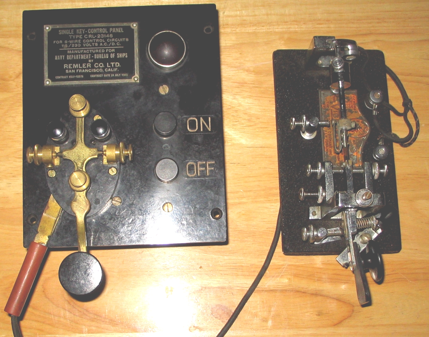
CAPH-26012B Key on 6-wire Control Unit

The 26012B key is an interesting one I picked up summer of 2005, which has some nice properties.  The contacts are isolated from the lever and other exposed hardware, which means no nasty shock when you reach blind for the key when it is hooked up to one of the many Navy transmitters that run 120/230V on the key.  Another interesting feature is the socket to insert a wedge for a speed key AKA "bug".  The 26012B key pictured above was installed on the 6-wire control unit by me, and it looks at home there.  The only thing I can't resolve is that there is a provision for grounding the lever through the left hand support, but there is no place for a ground wire to go through the top of the control unit.  Pictured with the key and control unit is a civilian "bug" by Vibroplex.